Heater with replaceable cartridge

a technology of catalytic heaters and cartridges, applied in the direction of capillary burners, burner details, pipe heating/cooling, etc., can solve the problems of only being removed and inoperable, heaters being inoperable for weeks, or even months, and achieve the effect of quick and easy replacemen

Active Publication Date: 2014-07-31
ALGAS SDI INT
View PDF3 Cites 4 Cited by
  • Summary
  • Abstract
  • Description
  • Claims
  • Application Information

AI Technical Summary

Benefits of technology

[0015]In some aspects, a main fuel supply line is coupled to the plenum chamber and is configured to deliver fuel to the chamber from the storage tank, or from another fuel supply. A fuel distribution header, having a fuel supply port coupled to the main fuel supply line, is positioned in the plenum chamber and is configured to deliver fuel to the plenum chamber. In some aspects, a heating element is positioned at least partially within the plenum chamber and is configured to heat the catalyst layer of the replaceable catalytic heater cartridge and to initiate combustion when fuel is supplied to the plenum chamber. After multiple or continuous uses of the heater, the heater cartridge can be quickly and easily replaced with a new cartridge for further use of the heater. Methods of replacing the cartridge and heating a tank with the replaceable cartridge are also provided, as further discussed below.

Problems solved by technology

Furthermore, the heater will only be removed and inoperable for a relatively short period of time while the cartridge is being replaced.
Current systems result in the heater being inoperable for weeks, or even months, while the sensitive catalytic material is merely replaced at a different location.

Method used


Image

  • Heater with replaceable cartridge
  • Heater with replaceable cartridge
  • Heater with replaceable cartridge

Examples


Embodiment Construction

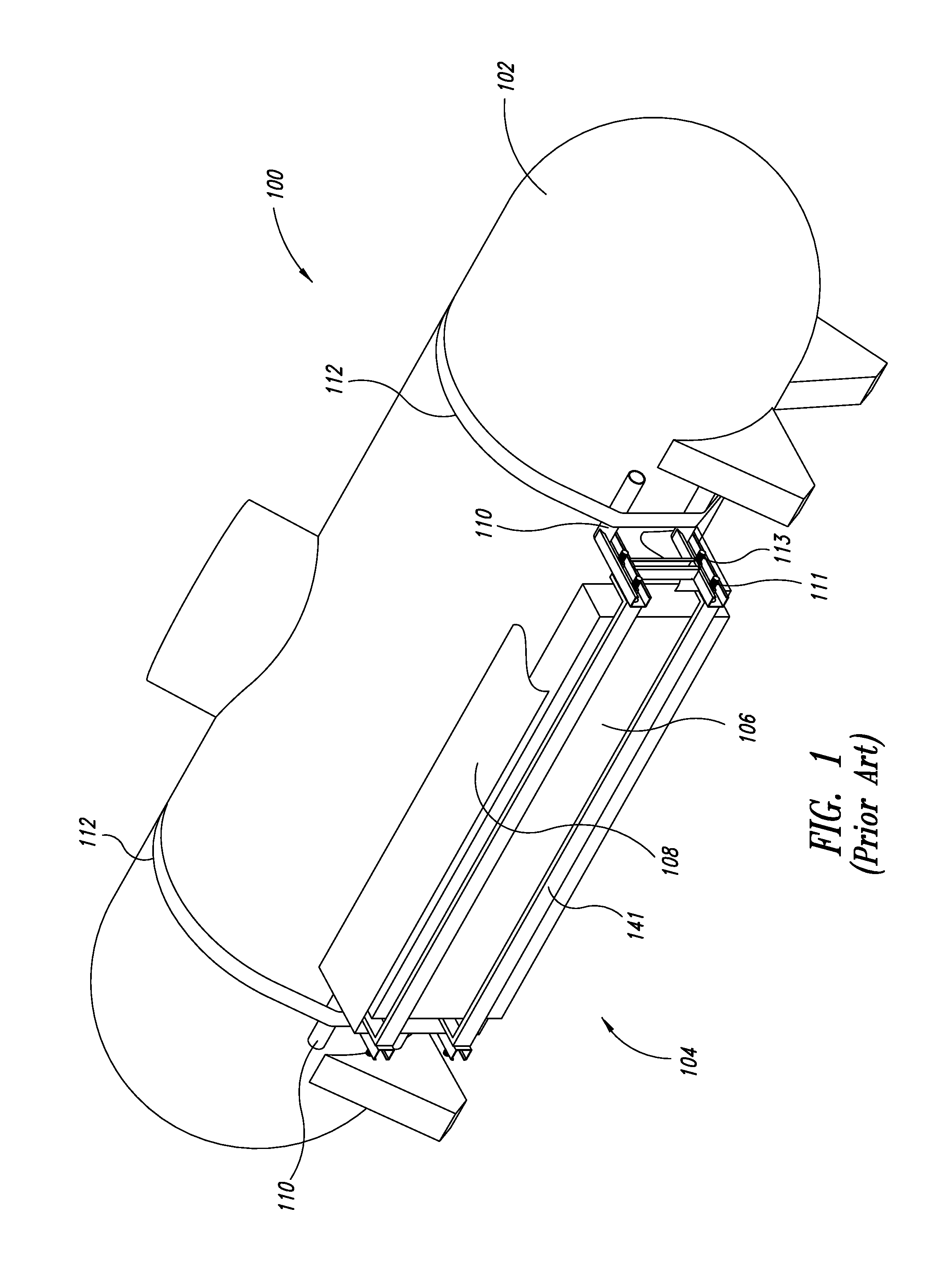
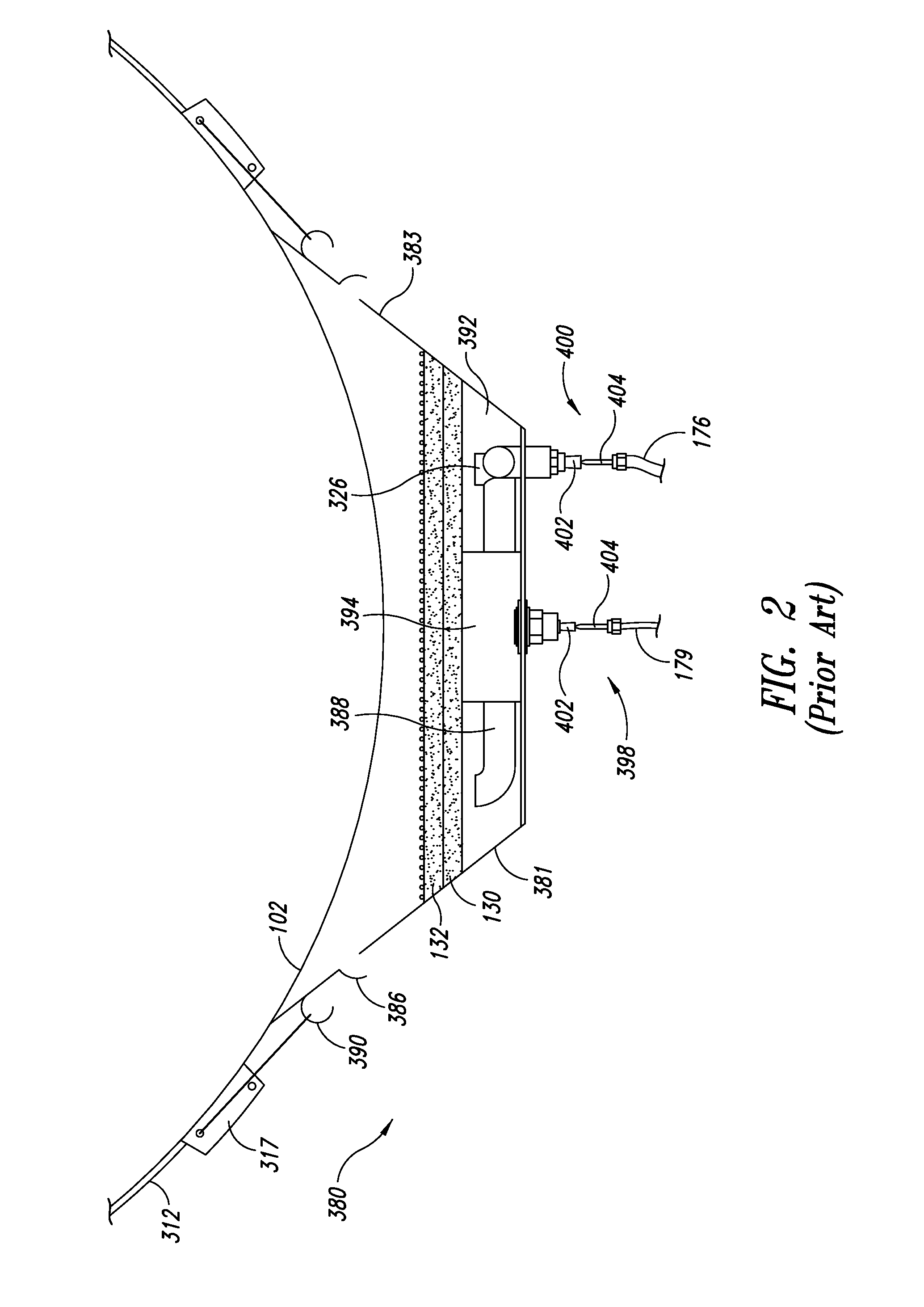
[0027]FIG. 1 shows an LPG storage system 100 according to an existing system, which was disclosed in U.S. patent application Ser. No. 13 / 162,363 (“the '363 application”), filed Jun. 16, 2011, which application is incorporated by reference in its entirety. System 100 includes an LPG tank 102 and a catalytic tank heater system 104. The heater system 104 includes a catalytic heater element 106, a shroud 108, mounting brackets 141, support frames 110, and straps 112. The support frames 110 are coupled to the tank 102 by the straps 112. The catalytic element 106 is coupled to the mounting brackets 141, which extend between the support frames 110, and are coupled thereto by first fasteners 111. The shroud 108 is coupled to the support frames 110 by second fasteners 113. FIG. 2 shows a tank heater system 380 coupled to a tank 102 according to an embodiment known in the prior art, as disclosed in the '363 application. The heater comprises a housing 383 that includes a plenum chamber 392, a ...


PUM

PropertyMeasurementUnit
temperatureaaaaaaaaaa
pressureaaaaaaaaaa
perimeteraaaaaaaaaa

Abstract

A catalytic tank heater includes a removably attached catalytic heater cartridge having catalytic material. The heater is attached to an LPG tank to position the catalytic heater cartridge to face the tank. The catalytic heater cartridge covers a plenum chamber of the catalytic tank heater. A fuel distribution header and heating element are positioned within the plenum chamber and are controlled to initiate combustion of the catalytic material to heat the tank. Vapor from the tank is provided as fuel to the catalytic tank heater, and is regulated to increase heat output as tank pressure drops. The catalytic heater cartridge can be replaced with a new cartridge while at the location of the tank on a property.

Description

BACKGROUND[0001]1. Technical Field[0002]Embodiments described in the present disclosure are directed generally to catalytic heaters having replaceable catalytic cartridges for heating applications.[0003]2. Description of the Related Art[0004]A number of fluids that are normally found in gaseous form are commonly stored and transported under pressure as liquids, including, for example, methane, butane, propane, butadiene, propylene, and anhydrous ammonia. Additionally, fuel gasses comprising one or more constituent gasses are also stored and transported under pressure as liquids, including, e.g., liquefied petroleum gas (LPG), liquefied natural gas (LNG), and synthetic natural gas (SNG). Of these, LPG is perhaps the most commonly used. Accordingly, the discussion that follows, and the embodiments described, refer specifically to LPG. Nevertheless, it will be understood that the principles disclosed with reference to embodiments for use with LPG tanks can be similarly applied to tanks...

Claims


Application Information

Patent Timeline
Patent Type & Authority Applications(United States)
IPC IPC(8): F17C7/04F17C13/02F23D14/18
CPCF17C7/04F23D14/18F17C13/025F23C13/02F23C2900/13001F23D2203/107F23D2213/00F23D2900/00003F17C2201/0114F17C2201/035F17C2201/054F17C2203/0617F17C2205/018F17C2205/0379F17C2221/035F17C2223/0153F17C2223/033F17C2225/0123F17C2225/035F17C2227/0302F17C2227/0386F17C2260/053F17C2270/0134F17C2270/0745Y10T29/4973Y10T137/6443
Inventor KIRBY, MICHAEL J.ZIMMER, GEORGE M.
Owner ALGAS SDI INT
Why Eureka
Try Eureka