Method and implant for stabilizing separated bone portions relative to each other

a technology of separated bone portions and implants, applied in the field of medical technology, to achieve the effect of enhancing mechanical stability, enhancing osseointegration, and suitable roughness or structur

Active Publication Date: 2014-07-31
WOODWELDING
View PDF59 Cites 26 Cited by
  • Summary
  • Abstract
  • Description
  • Claims
  • Application Information

AI Technical Summary

Benefits of technology

[0027]The peg and bridge assembly of the implant according to the invention are preferably made of a metal such as e.g. titanium or a titanium alloy or of a ceramic material such as e.g. aluminum oxide or zirconium oxide, but may also be made of a bio-degradable or non bio-degradable polymer material possibly containing a filler in form of fibers or particles for enhancing mechanical stability. If the peg and bridge assembly of the implant according to the invention are made of a non-degradable material and are designed for remaining in the patient's body, surfaces to be in contact with bone tissue are preferably equipped for enhancing osseointegration in a per se known manner by comprising a suitable roughness or structure and / or a suitable coating. Furthermore, such assemblies may comprise retention structures such as e.g. through openings or suitable surface structures which after a corresponding bone growth are suitable to form a positive fit connection in cooperation with the new bone tissue. If the implant is to be removed after healing of the cut or fracture or after fusion of the joint by osseoconduction, surfaces of the peg and bridge assembly are advantageously equipped for discouraging osseointegration (e.g. being polished) and the securing elements are made of a biodegradable material.

Problems solved by technology

Screw and plate systems are well established for stabilizing bone portions separated by a cut or fracture and for immobilizing joints, although they constitute severe constraints which in many cases prevent optimal solutions.

Method used


Image

  • Method and implant for stabilizing separated bone portions relative to each other
  • Method and implant for stabilizing separated bone portions relative to each other
  • Method and implant for stabilizing separated bone portions relative to each other

Examples


Embodiment Construction

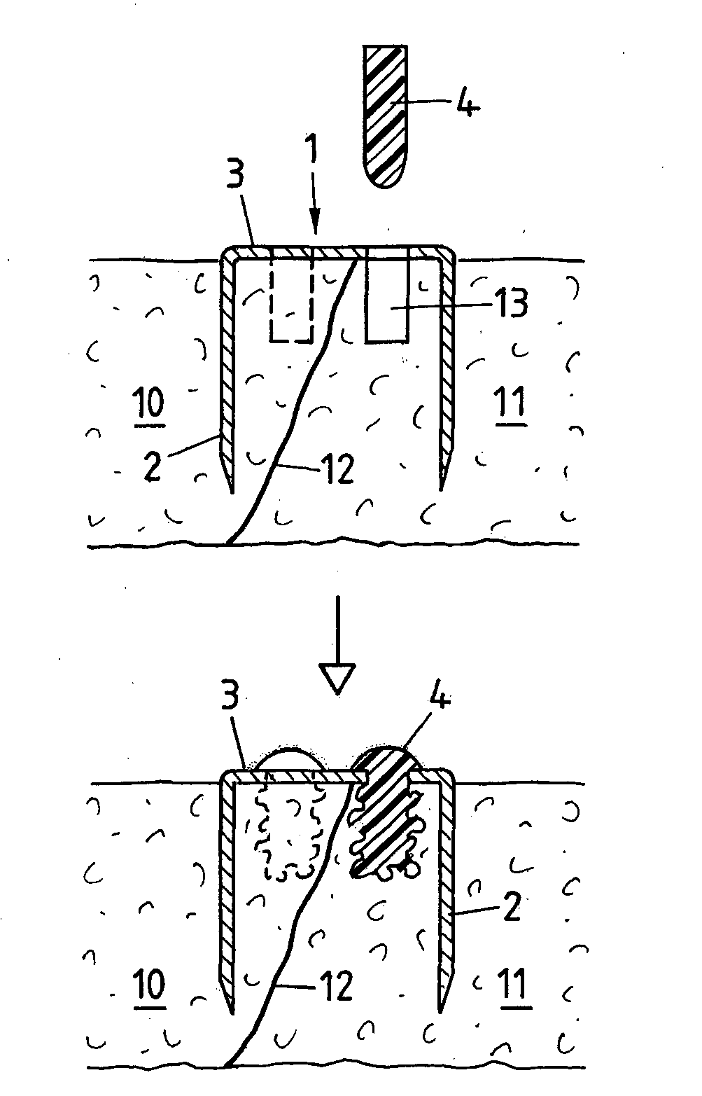
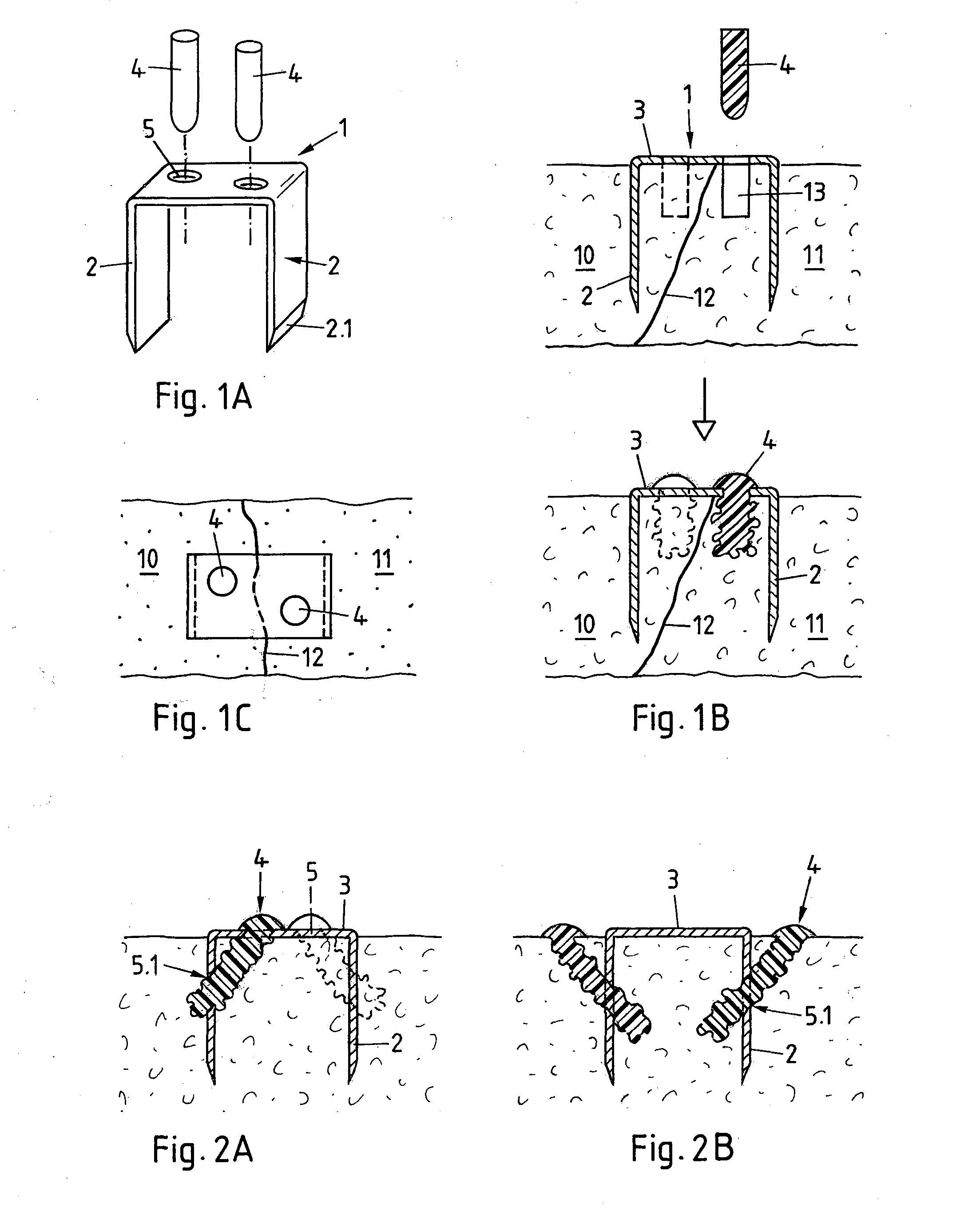
[0050]FIGS. 1A, 1B and 1C (FIGS. 1A / B / C) illustrate a first exemplary embodiment of the method and implant according to the invention, FIG. 1A showing the implant before implantation in a three dimensional illustration, FIG. 1B showing start (above) and end (below) of the implantation process in section parallel to the implantation direction, and FIG. 1C showing two separated bone portions being stabilized by the implant (viewed from above the bone surface).

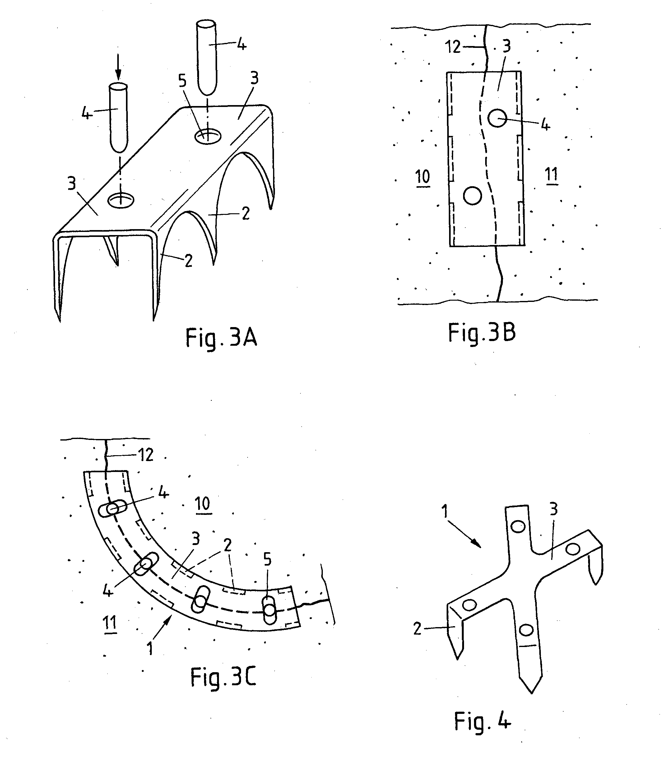
[0051]The implant comprises a peg and bridge assembly 1 with two peg portions 2 and one bridge portion 3, and it further comprises two securing elements 4 (or only one securing element 4). The peg and bridge assembly 1 is preferably made of a single piece of sheet material, preferably sheet metal, the peg portions 2 being bent out of the plane of the bridge portion 3 parallel to each other and preferably comprising sharpened distal edges 2.1 tapering in the direction of the thickness of the sheet material and / or tapering in the d...


PUM


Abstract

An implant for stabilizing two separated bone portions relative to each other an implant includes a peg, a bridge assembly and a securing element. The peg and bridge assembly include at least two peg portions and a bridge portion, wherein the bridge portion is arranged between the peg portions and wherein the peg and bridge portions are rigidly connected. The peg and bridge assembly is positioned relative to the bone portions such that one peg portion extends into the bone tissue of each one of the bone portions and the bridge portion extends across the gap separating the bone portions. The securing element is anchored in the bone tissue of one of the bone portions, its proximal end extending through an opening in an assembly portion extending parallel to a bone surface or across a notch in a proximal edge of an assembly portion.

Description

BACKGROUND OF THE INVENTION[0001]1. Field of the Invention[0002]The invention is in the field of medical technology and concerns a method and an implant for stabilizing a plurality of separated bone portions relative to each other in a human or animal patient, wherein the bone portions to be stabilized are in particular two bone portions being separated by osteotomy or fracture but may also be two originally articulating bones to be immobilized relative to each other (joint fusion, in particular fusion of small joints such as e.g. facet joints, finger or toe joints).[0003]2. Description of Related Art[0004]Osteotomy is a surgical procedure in which a bone is cut with the aim of being shortened, lengthened or re-aligned. Osteotomy is performed on human and animal patients mainly for realigning the load bearing surfaces in joints and for realigning bone portions in particular in the facio-maxillar region but also for re-aligning bone portions healed together with an undesired alignmen...

Claims


Application Information

Patent Timeline
Patent Type & Authority Applications(United States)
IPC IPC(8): A61B17/064
CPCA61B17/0642A61B17/68A61B17/84A61B2017/00955A61B2017/0641
Inventor MAYER, JORGWENGER, ANDREAS
Owner WOODWELDING
Why Eureka
Try Eureka