Power source system for vehicle, vehicle, and vehicle control method

a power source system and vehicle technology, applied in the direction of battery/fuel cell control arrangement, battery/cell control, instruments, etc., can solve the problem of unnecessarily restricting the charging of the low-voltage battery from the high-voltage battery, and achieve the effect of suppressing the power loss of the second power storage device more reliably

Active Publication Date: 2014-07-31
TOYOTA JIDOSHA KK
View PDF4 Cites 33 Cited by
  • Summary
  • Abstract
  • Description
  • Claims
  • Application Information

AI Technical Summary

Benefits of technology

[0007]Even when the vehicle is parked, the battery SOC can decrease due to self-discharge or power consumption on equalization among the cells. In the above-mentioned charging control device, the lower limit value of the SOC of the high-voltage battery is set with consideration for such decrease in the SOC. However, where the lower limit value of the SOC is set to an unnecessarily high value to prevent the high-voltage battery from overdischarge, the charging of the low-voltage battery from the high-voltage battery can be unnecessarily restricted. As a result, the frequency of cases in which the low-voltage battery is depleted (flat battery) can increase.
[0008]The invention relates to a power source system for a vehicle, which includes a first power storage device that stores power for running the vehicle, and a second power storage device, which stores power for auxiliary devices, and provides a technique for more reliably suppressing the depletion of power in the second power storage device.
[0019]With the above-described features, the decrease amount of the state amount of the first power storage device is estimated within a period from after the parking time of the vehicle exceeds the predetermined period of time until the vehicle is started. The lower limit of the state amount of the first power storage device is set based on the estimated decrease amount. Thus, it is not necessary to set an unnecessarily high lower limit of the state amount in order to prevent the first power storage device from overdischarge, and whether or not to perform charging control of the second power storage device can be adequately determined by taking into account the decrease amount of the state amount within the period of time until the vehicle is started. Therefore, the depletion of power in the second power storage device can be suppressed more reliably.

Problems solved by technology

However, where the lower limit value of the SOC is set to an unnecessarily high value to prevent the high-voltage battery from overdischarge, the charging of the low-voltage battery from the high-voltage battery can be unnecessarily restricted.

Method used


Image

  • Power source system for vehicle, vehicle, and vehicle control method
  • Power source system for vehicle, vehicle, and vehicle control method
  • Power source system for vehicle, vehicle, and vehicle control method

Examples


embodiment 1

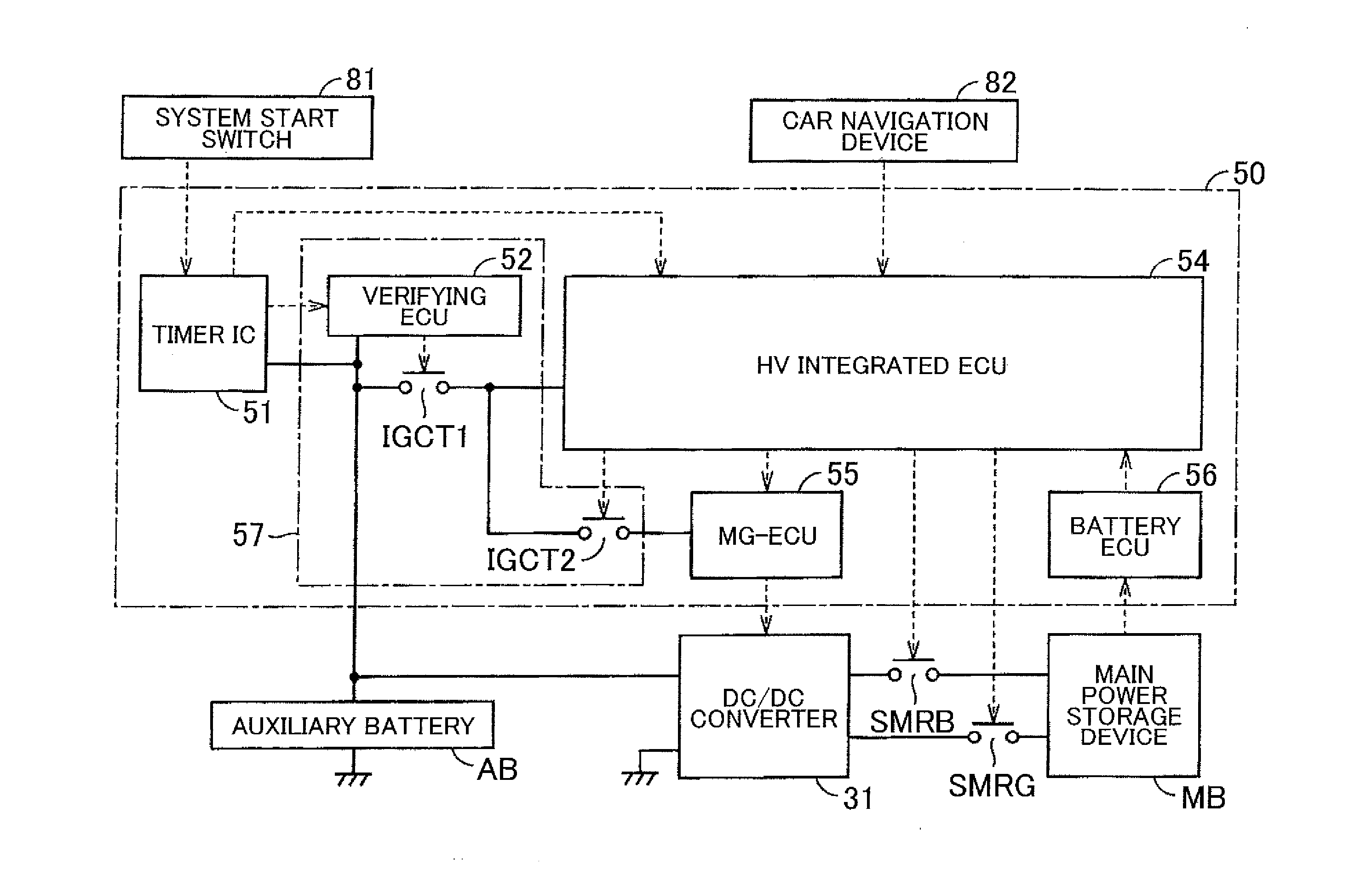
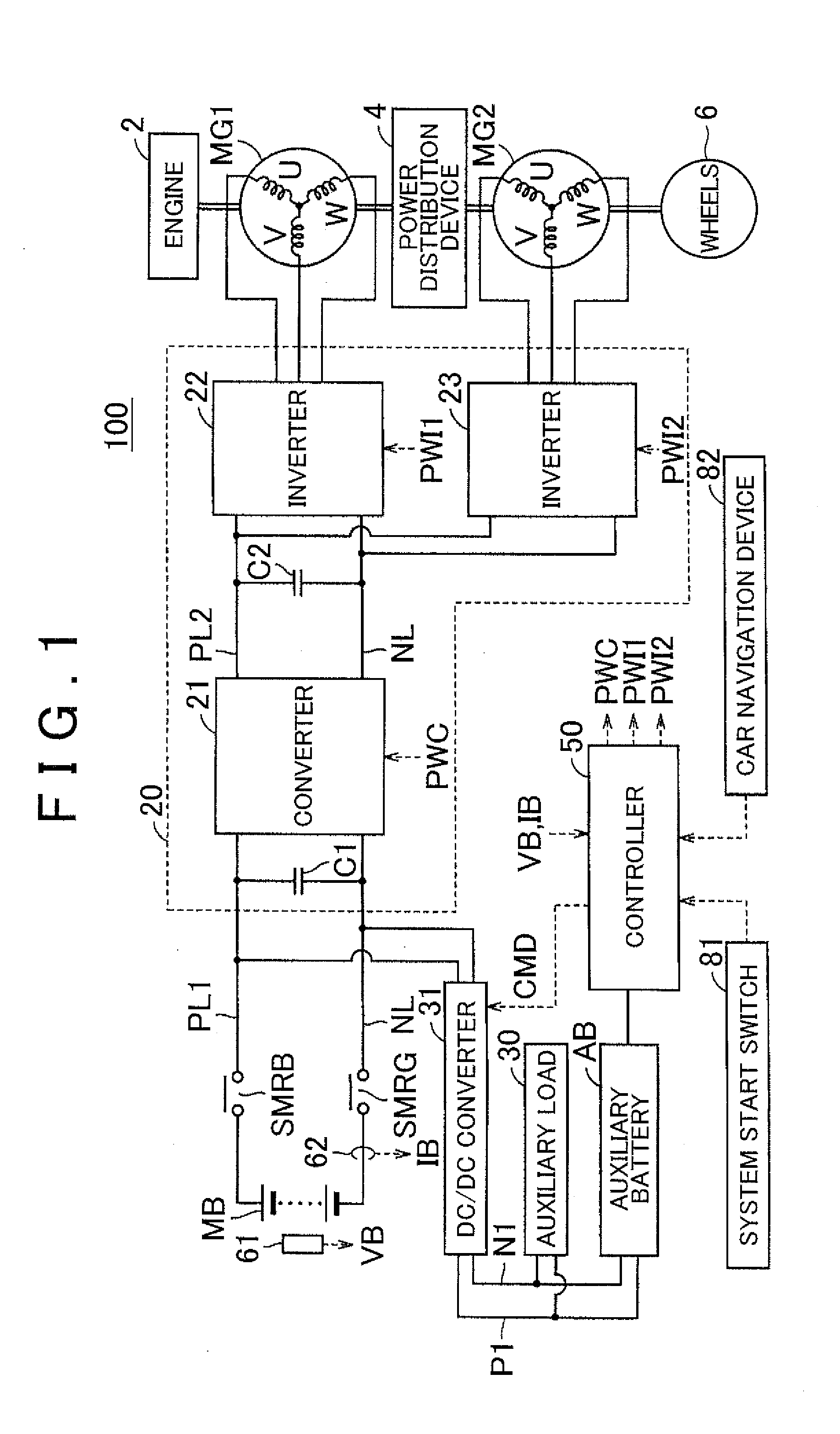
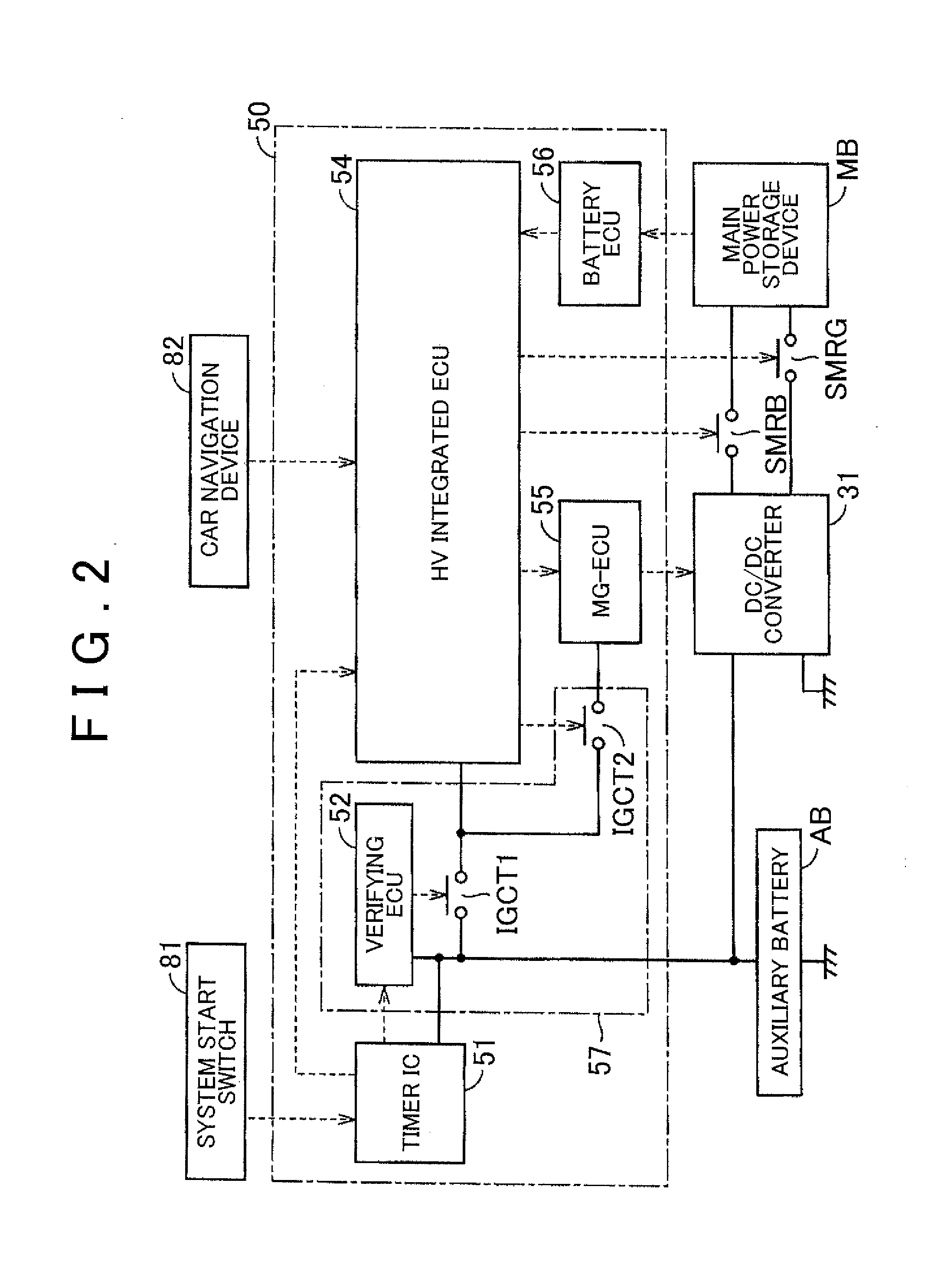
[0030]FIG. 1 illustrates the configuration of a vehicle carrying the power source system of the invention. Referring to FIG. 1, a vehicle 100 is provided with an engine 2, motor generators (MGs), i.e., MG1 and MG2, a power distribution device 4, wheels 6, a power control unit (PCU) 20, a main power storage device MB, system main relays SMRB, SMRG, a voltage sensor 61, and a current sensor 62. The vehicle 100 is also provided with an auxiliary battery AB, an auxiliary load 30, a direct current / direct current (DC / DC) converter 31, a controller 50, a system start switch 81, and a car navigation device 82.

[0031]The vehicle 100 carries the MG1, MG2 and the engine 2 as drive sources. The power distribution device 4 connects the drive shaft of the engine 2, the MG1, and the drive shaft of the wheels 6. The power generated by the engine 2 is distributed by the power distribution device 4 to two paths, namely, a path for transmitting power to the drive shaft of the wheels 6 and a path for t...

embodiment 2

[0077]FIG. 6 shows the entire configuration of the vehicle carrying the power source system according to Referring to FIG. 6, a vehicle 100A has the configuration of the vehicle 100 shown in FIG. 1 which is further provided with an outside air temperature sensor 71 and in which a controller 50A is used instead of the controller 50.

[0078]The outside air temperature sensor 71 detects the outside air temperature around the vehicle 100A and outputs the detected value to the controller 50A. The detected value of the outside air temperature sensor 71 is used to estimate the temperature of the engine 2 and the main power storage device MB when it is determined whether the charging of the auxiliary battery AB can be executed while the vehicle is parked. An engine water temperature sensor that detects the temperature of cooling water of the engine 2, and / or a temperature sensor that detects the temperature of the main power storage unit MB may be used instead of the outside air temperature ...


PUM


Abstract

A power source system for a vehicle includes a first power storage device, a second power storage device, a voltage converter, and a controller. The controller is configured to (a) execute a charging control in which the second power storage device is charged by the voltage converter when a parking time of the vehicle exceeds a predetermined period of time, (b) estimate a decrease amount in a state of charge of the first power storage device in a time period from after elapse of the predetermined period of time until a start of the vehicle, (c) set a lower limit of the state of charge based on the decrease amount, and (d) not execute the charging control when the state of charge is lower than the lower limit.

Description

INCORPORATION BY REFERENCE[0001]The disclosure of Japanese Patent Application No. 2013-011793 filed on Jan. 25, 2013 including the specification, drawings and abstract is incorporated herein by reference in its entirety.BACKGROUND OF THE INVENTION[0002]1. Field of the Invention[0003]The invention relates to a power source system for a vehicle, a vehicle, and a vehicle control method.[0004]2. Description of Related Art[0005]Japanese Patent Application Publication No. 2010-206885 (JP 2010-206885 A) discloses a charging control device for a vehicle that can charge a low-voltage battery, which supplies power to onboard electric components, from a high-voltage battery which is a power source of the vehicle. In such a charging control device, where the voltage of the low-voltage battery is equal to or lower than a predetermined threshold in a power feed mode in which the vehicle does not run, the low-voltage battery is charged using the power stored in the high-voltage battery.[0006]In th...

Claims


Application Information

Patent Timeline
Patent Type & Authority Applications(United States)
IPC IPC(8): B60W20/00B60W10/08B60W10/06B60L50/16
CPCB60W20/00Y10S903/93B60W10/08B60W10/06B60K6/445B60W10/26B60W30/18054B60W2510/244B60W20/13H02J7/0013Y02T10/92B60L50/62B60L50/16B60L58/13B60L58/20H02J7/0048H02J2310/48H02J2310/46B60L58/15Y02T10/62Y02T10/70Y02T10/7072H02J1/082
Inventor SUGIYAMA, YOSHINOBU
Owner TOYOTA JIDOSHA KK
Why Eureka
Try Eureka