Machine and method for marking articles

a marking machine and marking technology, applied in the field of machine and a marking method, can solve the problems of increased rigidity and more significant shape defects, unsuitable support means and fixed support rollers, and too large overhang span between the means supporting the ends

Active Publication Date: 2014-08-07
ILLINOIS TOOL WORKS INC
View PDF10 Cites 1 Cited by
  • Summary
  • Abstract
  • Description
  • Claims
  • Application Information

AI Technical Summary

Benefits of technology

[0013]Thus, the invention enables the improvement of the positioning of the article during its marking, and thereby the improvement of the quality of this marking. According to the invention, the support system and the carriage turret / s of the positioning system make it possible to define the reference position of the article in view of its marking and then, thanks to their being independently movable, to adapt to its shape defects during marking. If during this marking, the machine included one or more carriage turret or turrets fixed along the axis of marking, as well as supporting rollers fixed relative to each other, the support rollers would not be in contact at all times with the article and could not counter the marking force satisfactorily. The machine according to the invention is particularly suitable for hot stamping of articles, in particular of glass containers.

Problems solved by technology

Without the support rollers, the overhang span between the means for supporting the ends might be too large.
However, when the container is made of glass, metal or plastic material and has relatively thick walls, it has greater rigidity and more significant shape defects than a plastic container with thin walls.
In this case, the support means and fixed support rollers are not suitable.

Method used


Image

  • Machine and method for marking articles
  • Machine and method for marking articles
  • Machine and method for marking articles

Examples


Embodiment Construction

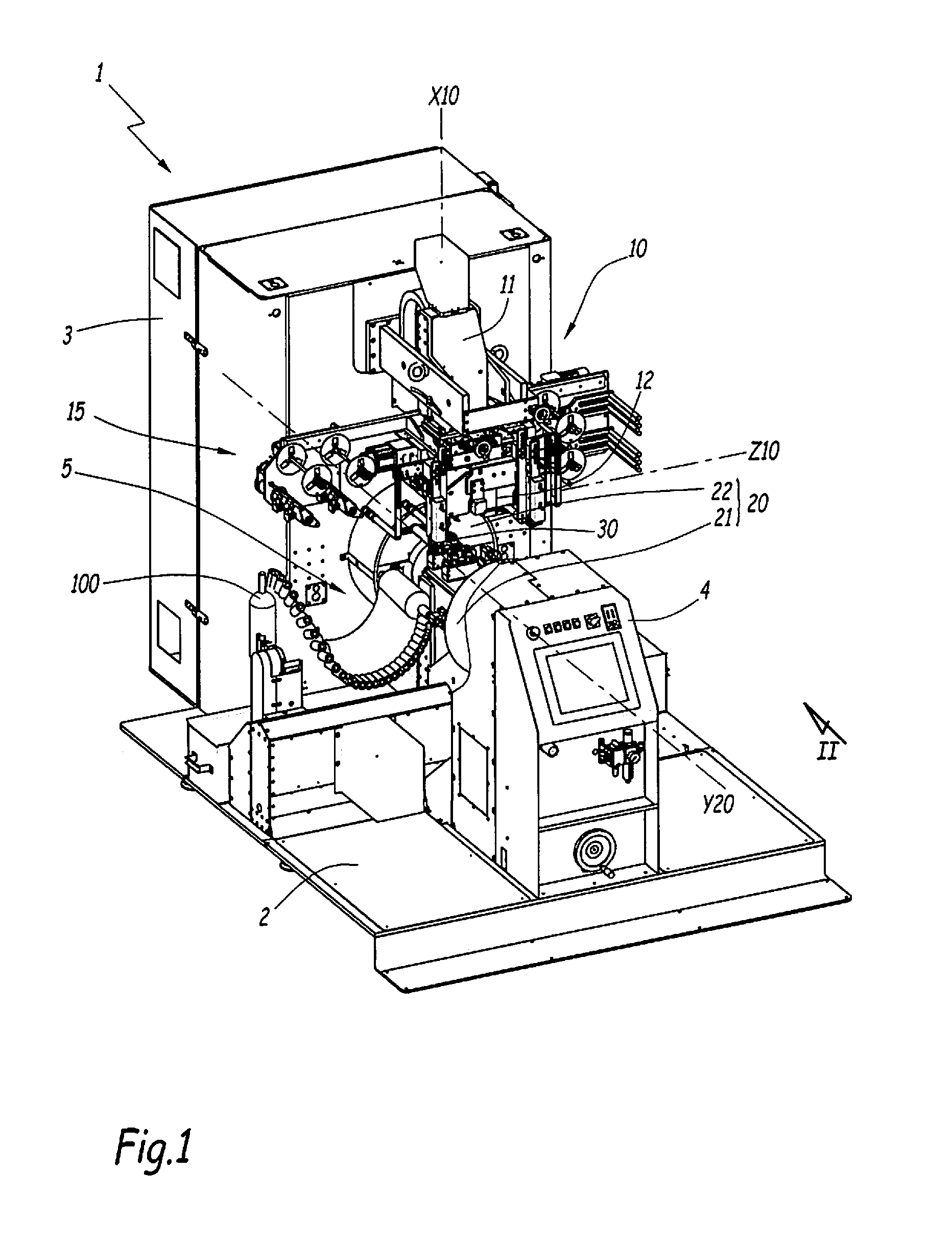
[0036]The machine 1 is intended to be used for decorating articles 100 by way of applying a marking on the external surface. In particular, the machine 1 is suitable for the hot stamp marking of containers 100.

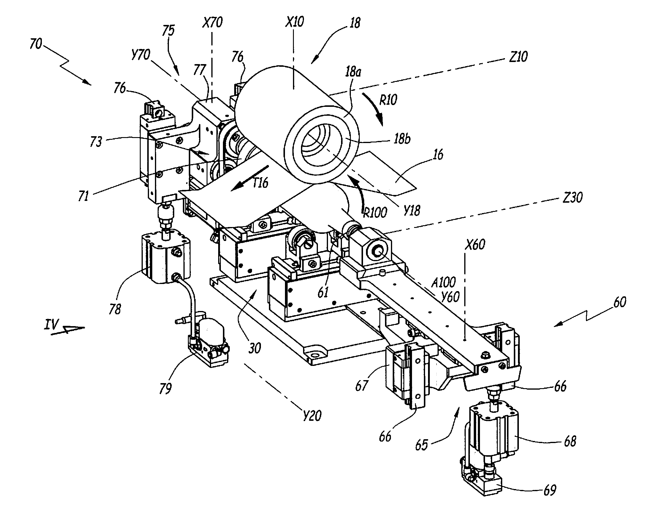
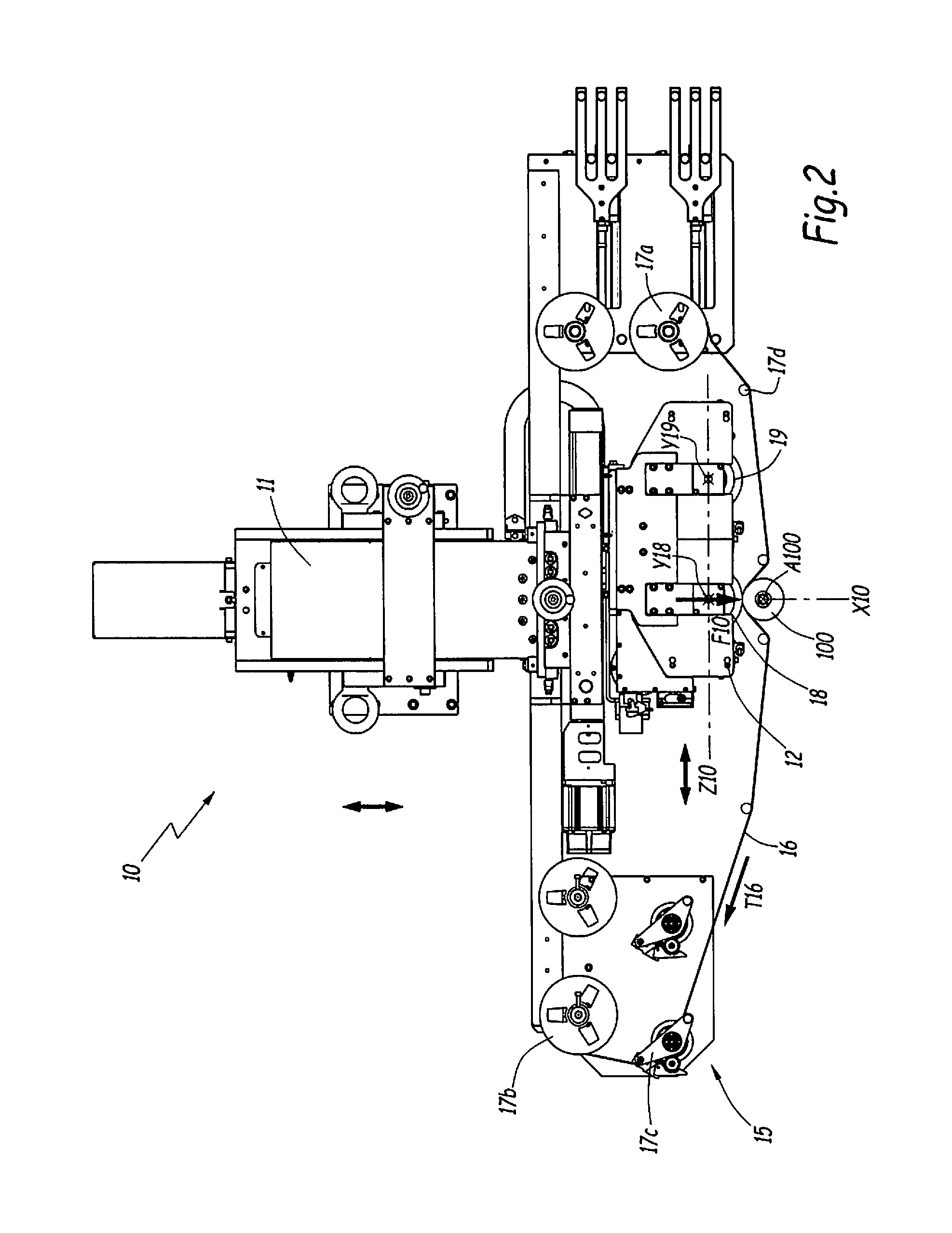
[0037]The machine 1 comprises a base 2 for ground anchoring, an electrical cabinet 3, a control station 4, a system 5 for feeding the machine 1 with containers 100, a marking head 10, a system 20 for transporting and positioning of containers 100 so as to face the marking head 10, from the feeding system 5, as well as a system 30 for supporting the container 100 during the marking process. The housing for the electrical cabinet 3 and the housing for the control station 4 are fixed at the base 2. The machine 1 also comprises a system for unloading the marked containers 100, this system is not shown for the sake of simplification.

[0038]In the example in FIGS. 1 to 6, the containers 100 are glass bottles of a generally cylindrical shape. The containers 100 extend along a central ...


PUM

PropertyMeasurementUnit
diameteraaaaaaaaaa
lengthaaaaaaaaaa
degree of freedomaaaaaaaaaa

Abstract

The present invention relates to a machine for marking articles that includes a marking head applying a marking force on an article along to a first axis; a positioning system positioning the article facing the marking head and generally along a perpendicular second axis; and a support system supporting the article during marking by the marking head. The positioning system comprises at least one carriage-turret for supporting the article. When the article is positioned facing the marking head by the at least one carriage-turret, this carriage-turret has a degree of freedom along a direction parallel to the first axis. The support system and / or the at least one carriage-turret includes backlash means along a direction parallel to a perpendicular third axis, to compensate for the shape defects of the article during application of the marking force.

Description

CROSS-REFERENCE TO RELATED APPLICATIONS[0001]This application claims priority to French Patent Application 1350937, filed 4 Feb. 2013, and titled “MACHINE ET PROCEDE DE MARQUAGE D'ARTICLES,” the entire disclosure of which is incorporated by reference.TECHNICAL FIELD[0002]The present invention relates to a machine and a method for marking articles, in particular by hot stamp marking. The field of the invention is that of marking rigid articles such as containers, for example made of glass, metal or plastic, with thick walls.BACKGROUND[0003]In a known manner, a marking machine includes a marking head fitted with at least one marking member, of the roller or punch type. The marking head is configured to apply a marking force on an article, in particular a container, by means of the marking member. The interposition of a marking tape between the marking head and the container makes it possible to create a pattern on the outer surface of the container, or indeed the interposition of a la...

Claims


Application Information

Patent Timeline
Patent Type & Authority Applications(United States)
IPC IPC(8): B21D22/02
CPCB21D22/022B41F16/0026B41F16/0086B41F17/002B41F17/18B41P2217/62
Inventor DEMANGE, FLORENTTARNOWSKI, VINCENT
Owner ILLINOIS TOOL WORKS INC
Why Eureka
Try Eureka