
Dye-Sensitized Solar Cell via Co-Sensitization with Cooperative Dyes

a solar cell and dye technology, applied in the field of dye-sensitive light absorbing chemistry, can solve the problems of many sensitizing dyes suffering from a deficiency in optical absorption beyond 700 nanometers (nm), and the choice of sensitizer is typically limited, so as to enhance the photovoltaic performance of dye-sensitized solar cells (dscs), the effect of increasing the photovoltaic response and improving the performance of dsc prototypes fabricated

Inactive Publication Date: 2014-08-07
SHARP LAB OF AMERICA INC SLA
View PDF3 Cites 2 Cited by
  • Summary
  • Abstract
  • Description
  • Claims
  • Application Information

AI Technical Summary

Benefits of technology

The patent describes a way to improve the performance of dye-sensitized solar cells by using two different types of dyes, called porphyrins and ruthenium polypyridyl complexes. These two dyes work together to enhance the cell's ability to capture sunlight and convert it into electricity. This effect is especially important in the short and intermittent regions of the optical spectrum. The co-sensitization strategy can be easily implemented using a "one pot" approach, and the resulting solar cells perform better than cells made with either dye alone. The ratio of the two dyes can be controlled based on their adsorption rates. Overall, this technology provides a way to improve the efficiency of dye-sensitized solar cells.

Problems solved by technology

The technical problem addressed in this patent text is how to improve the efficiency of dye-sensitized solar cells by combining multiple dyes that can work together to increase both the amount of light absorbed and the range of wavelengths over which they operate.

Method used


Image

  • Dye-Sensitized Solar Cell via Co-Sensitization with Cooperative Dyes
  • Dye-Sensitized Solar Cell via Co-Sensitization with Cooperative Dyes
  • Dye-Sensitized Solar Cell via Co-Sensitization with Cooperative Dyes

Examples


Embodiment Construction

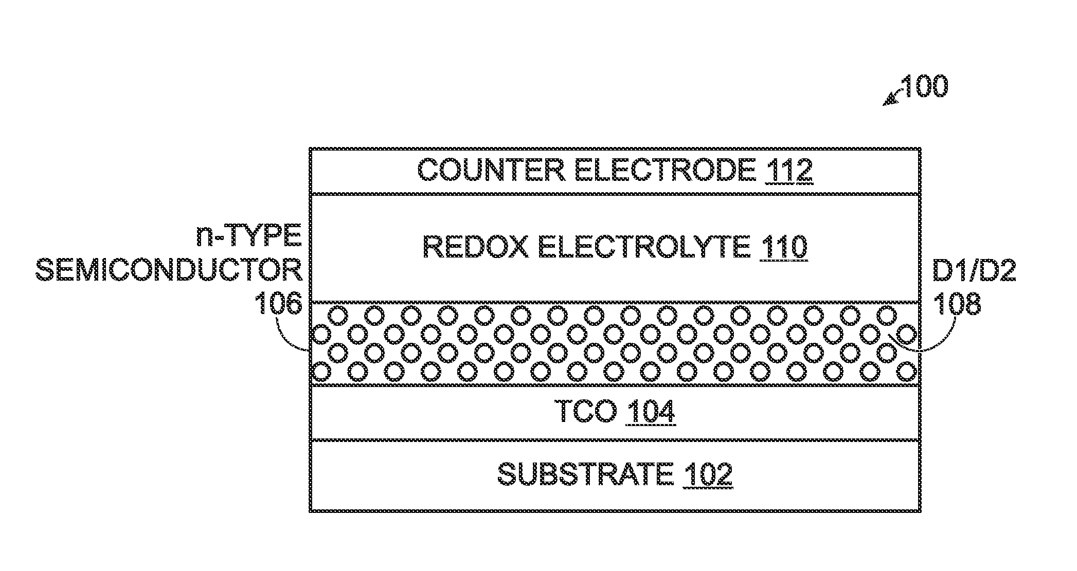
[0053]FIG. 1 is a partial cross-sectional view of a co-sensitized dye-sensitized solar cell (DSC). The DSC 100 comprises a transparent substrate 102, such as glass, and a transparent conductive oxide (TCO) film 104 overlying the transparent substrate 102. Some examples of TCO materials include fluorine-doped tin oxide (FTO) and indium tin oxide (ITO). An n-type semiconductor layer 106 overlies the TCO film 104. The n-type semiconductor layer 106 is co-sensitized with a first dye (D1) and a second dye (D2), as represented by reference designator 108. That is, both dyes can independently inject electrons into the n-type semiconductor following illumination. Some examples of n-type semiconductor layer 106 materials include metal oxides of titanium (TiO2), aluminum (Al2O3), tin (SnO2), magnesium (MgO), tungsten (WOa), niobium (Nb2O5), and mixed metal oxides including more than one type of metal. The co-sensitized n-type semiconductor layer 106 may take the form of nanoparticles, nanotub...


PUM

PropertyMeasurementUnit
Electrical conductoraaaaaaaaaa
Absorbanceaaaaaaaaaa
Transparencyaaaaaaaaaa

Abstract

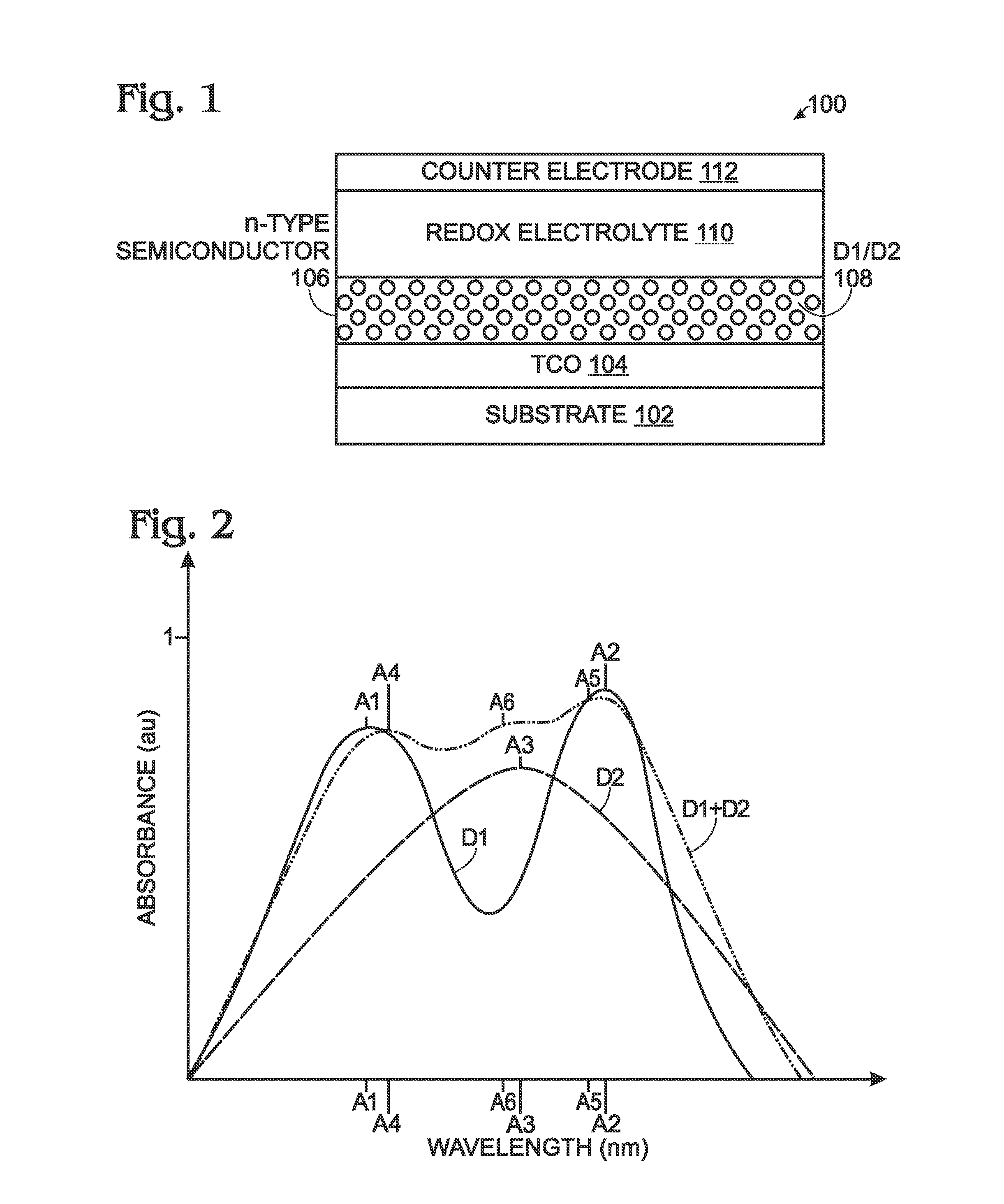
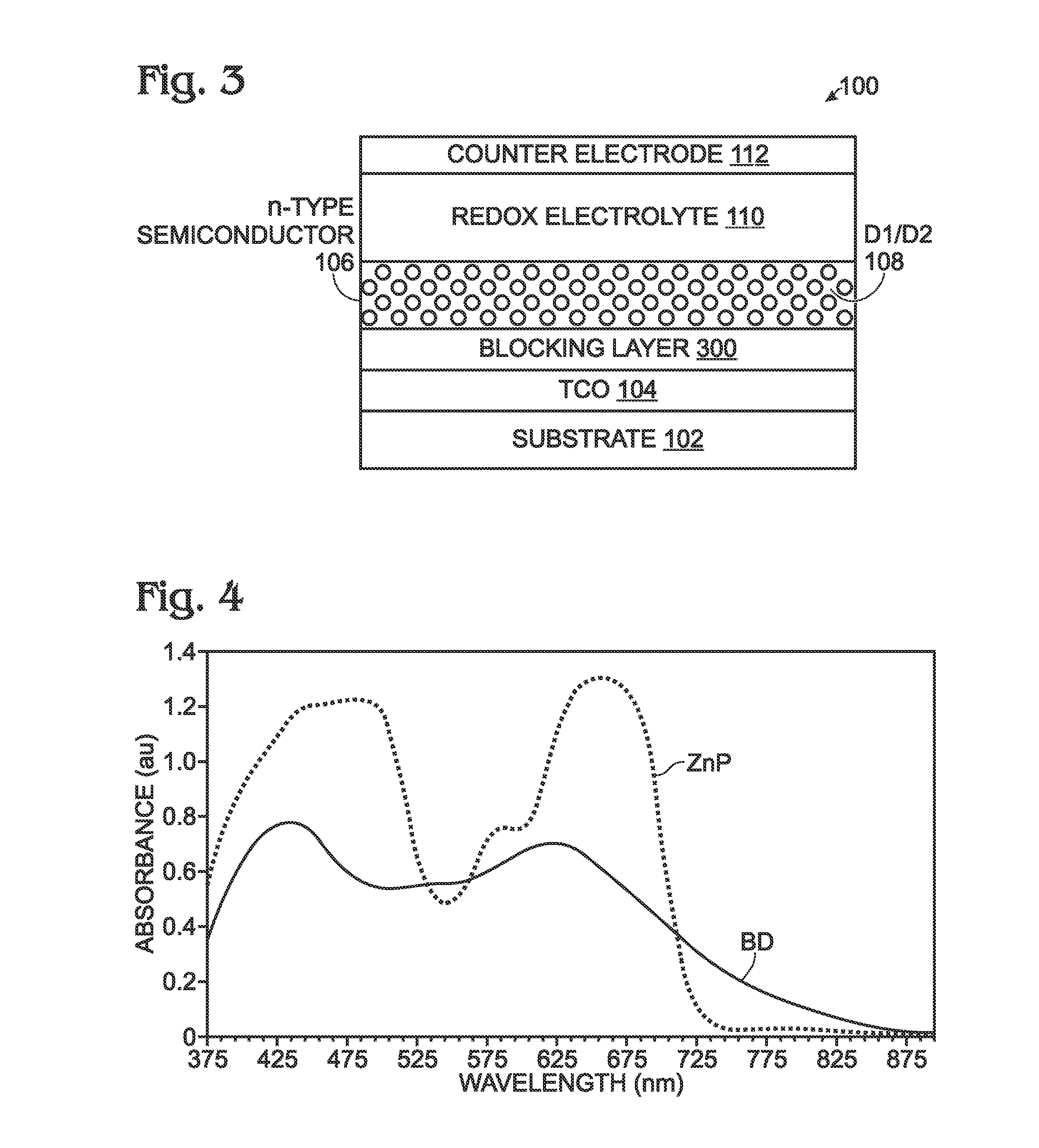
A co-sensitized dye-sensitized solar cell (DSC) is provided, made from a transparent substrate and a transparent conductive oxide (TCO) film overlying the transparent substrate. An n-type semiconductor layer overlies the TCO, and is co-sensitized with a first dye (D1) and a second dye (D2). A redox electrolyte is in contact with the co-sensitized n-type semiconductor layer, and a counter electrode overlies the redox electrolyte. The first dye (D1) has a first optical absorbance local maxima at a first wavelength (A1) and a second optical absorbance local maxima at a second wavelength (A2), longer than the first wavelength. The second dye (D2) has a third optical absorbance local maxima at a third wavelength (A3) between the first wavelength (A1) and the second wavelength (A2). In one aspect, the first dye (D1) includes a porphyrin material, for example, a metalloporphyrin obtained by complexation with a transition metal such as zinc (i.e. zinc porphyrin (ZnP)).

Description


Claims


Application Information

Patent Timeline
Owner SHARP LAB OF AMERICA INC SLA
Learn More