Display Device

a technology of a display device and a display plate, which is applied in the field of display devices, can solve the problems of increasing the number of components, unable to be stably incident on the light guide plate, and the stably kept

Inactive Publication Date: 2014-08-07
FUNAI ELECTRIC CO LTD
View PDF2 Cites 12 Cited by
  • Summary
  • Abstract
  • Description
  • Claims
  • Application Information

AI Technical Summary

Benefits of technology

[0008]The present invention has been proposed in order to solve the aforementioned problem, and an object of the present invention is to provide a ...

Problems solved by technology

In the liquid crystal display module according to the aforementioned Japanese Patent Laying-Open No. 2007-026916, however, an interval between the light incident surface of the light guide plate and the LEDs mounted on the PCB cannot be stably kept at a prescribed interval when no spacer member is provided between she light guide plate and the PCB, and hence the light emitted from the LEDs ca...

Method used


Image

  • Display Device
  • Display Device
  • Display Device

Examples


first embodiment

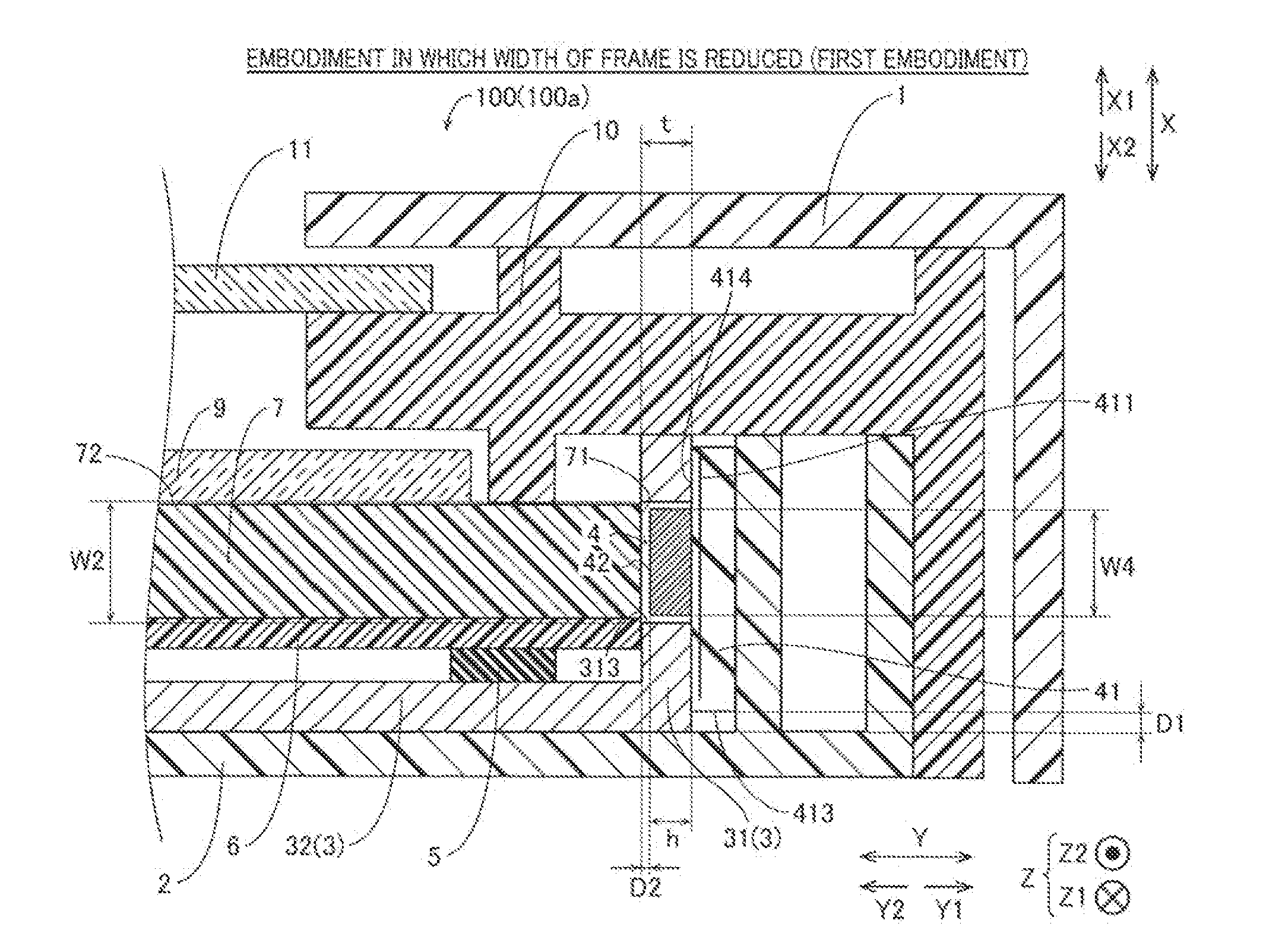
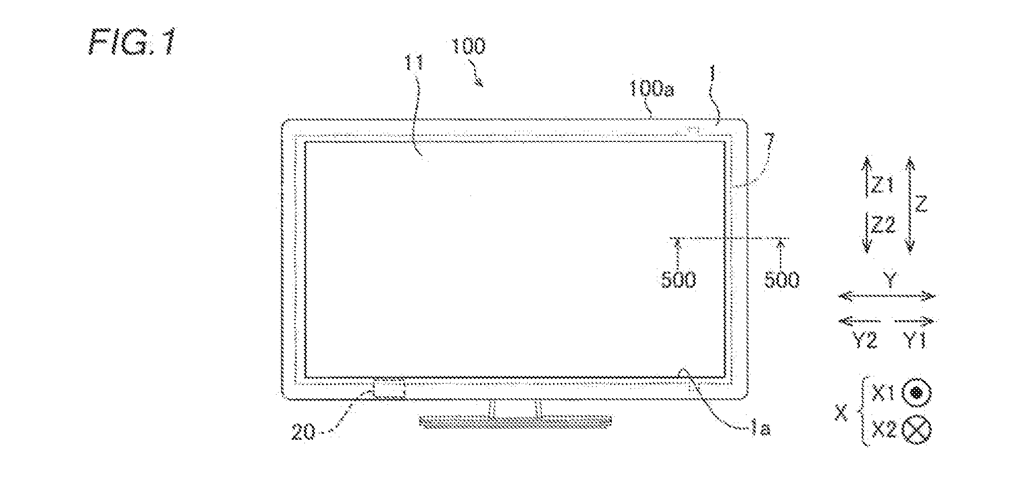
[0042]The structure of a TV (television set) 100 according to a first embodiment of the present invention is now described with reference to FIGS. 1 to 5. The TV 100 is an example of the “display device” in the present invention.

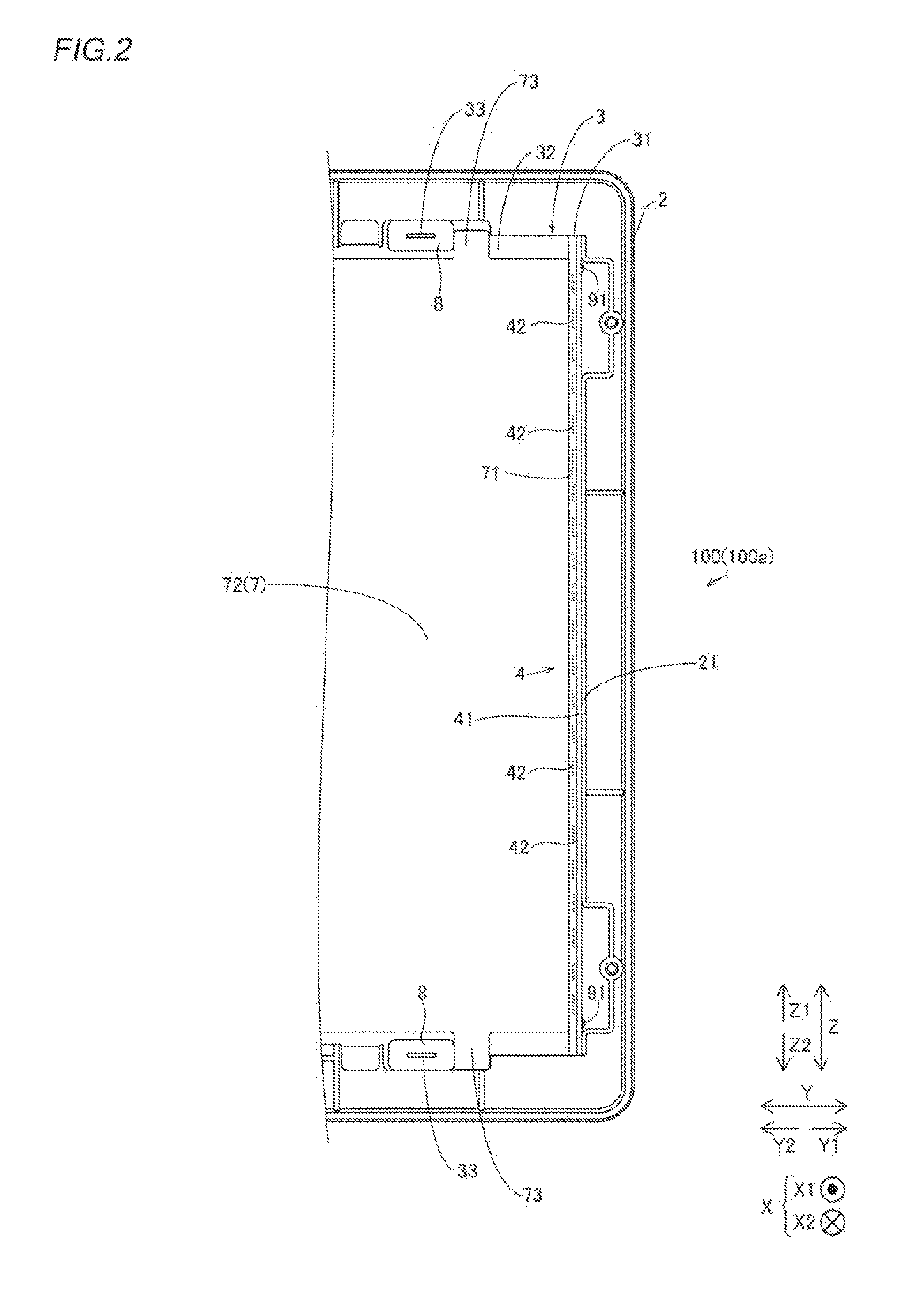
[0043]The TV 100 according to the first embodiment of the present invention includes a front frame 1 and a rear frame 2 (see FIG. 2), as shown in FIG. 1. A display portion 11 displaying an image is exposed from an opening 1a of the front frame 1. The TV 100 is configured to be capable of receiving a broadcast signal through a receiving portion 20.

[0044]Inside the TV 100, a heat sink 3 and an LED module 4 including a plurality of LEDs 42 (see FIG. 2) are provided, as shown in FIGS. 2 and 4. As shown in FIG. 4, a supporting member 5, a reflective sheet 6, a light guide plate 7, silicon rubbers 8 (see FIG. 2), and an optical sheet 9 are arranged on the front side (X1 side) of the heat sink 3. On the front side of she light guide plate 7, a resin frame 10 is arr...

second embodiment

[0073]The structure of a TV 200 according to a second embodiment of the present invention is now described with reference to FIG. 6. The TV 200 is an example of the “display device” in the present invention.

[0074]In this second embodiment, the TV 200 has a light guide plate 107 extending to the outside of a TV body 200a and being largely formed, unlike in the first embodiment in which the spacer portion 31 and the LEDs 42 overlap with each other, so that the width of the frame of the TV body 100a is reduced. The TV body 200a is an example of the “display device body” in the present invention.

[0075]As shown in FIG. 6, the TV 200 according to the second embodiment includes a front frame 101 and a rear frame 102. Inside the TV 200, a heat sink 103 and an LED module 4 including a plurality of LEDs 42 are provided. Furthermore, a supporting member 5, a reflective sheet 6, the light guide plate 107, and an optical sheet 9 are arranged on the front side (X1 side) of the heat sink 103. On t...


PUM


Abstract

A display device includes a display device body, a display portion arranged on the front side, a light source, a light source substrate, a light guide plate having a light incident surface, and a heat sink arranged to be opposed to the light incident surface of the light guide plate between the light guide plate and the light source substrate, including a light source arrangement hole configured to arrange the light source and a spacer portion arranged to be opposed to the light incident surface of the light guide plate between the light guide plate and the light source substrate and keeping an interval between the light incident surface of the light guide plate and the light source at a prescribed interval.

Description

BACKGROUND OF THE INVENTION[0001]1. Field of the Invention[0002]The present invention relates to a display device, and more particularly, it relates to a display device including a light guide plate and a heat sink.[0003]2. Description of the Background Art[0004]A display device including a light guide plate and a heat sink is known in general, as disclosed in Japanese Patent Laying-Open No. 2007-026916, for example.[0005]The aforementioned Japanese Patent Laying-Open No. 2007-026916 discloses a liquid crystal display module (display device) including a liquid crystal display module body (display device body) and a liquid crystal display panel (display portion) arranged on the front side of the liquid crystal display module body, displaying an image. This liquid crystal display module includes LEDs (light source) supplying light, to the liquid crystal display panel, a PCB (light source board) mounted with the LEDs, and a light, guide plate having a light incident surface receiving l...

Claims


Application Information

Patent Timeline
IPC IPC(8): F21V8/00H04N5/64
CPCG02B6/0085H04N5/64G02B6/009G02B6/0073
Inventor SASAOKA, HIROMASAKONO, AKIFUMI
Owner FUNAI ELECTRIC CO LTD
Why Eureka
Try Eureka