Picture coding device, picture coding method, picture coding program, picture decoding device, picture decoding method, and picture decoding program

a technology of coding devices and motion information, applied in the field of coding moving pictures, can solve the problems of increasing the number of accesses to the memory storing coding information already coded, less efficient coding, and increasing the number of code accesses, so as to reduce the load required to process motion information and improve the efficiency of coding motion information

Active Publication Date: 2014-08-07
JVC KENWOOD CORP A CORP OF JAPAN
View PDF1 Cites 80 Cited by
  • Summary
  • Abstract
  • Description
  • Claims
  • Application Information

AI Technical Summary

Benefits of technology

[0013]The embodiment addresses the aforementioned issue, and a purpose thereof is to provide a technology capabl...

Problems solved by technology

Therefore, if the prediction fails, the difference between motion vectors will grow accordingly, resulting in an increase in the code size.
Therefore, even if a given block has the same motion information as an immediately neighboring block, the information is coded in a duplicate manner, resulting in less efficient coding.
However, since the positions of neighboring blocks referred to differ according to the techniques, the number of accesses to the me...

Method used


Image

  • Picture coding device, picture coding method, picture coding program, picture decoding device, picture decoding method, and picture decoding program
  • Picture coding device, picture coding method, picture coding program, picture decoding device, picture decoding method, and picture decoding program
  • Picture coding device, picture coding method, picture coding program, picture decoding device, picture decoding method, and picture decoding program

Examples


first embodiment

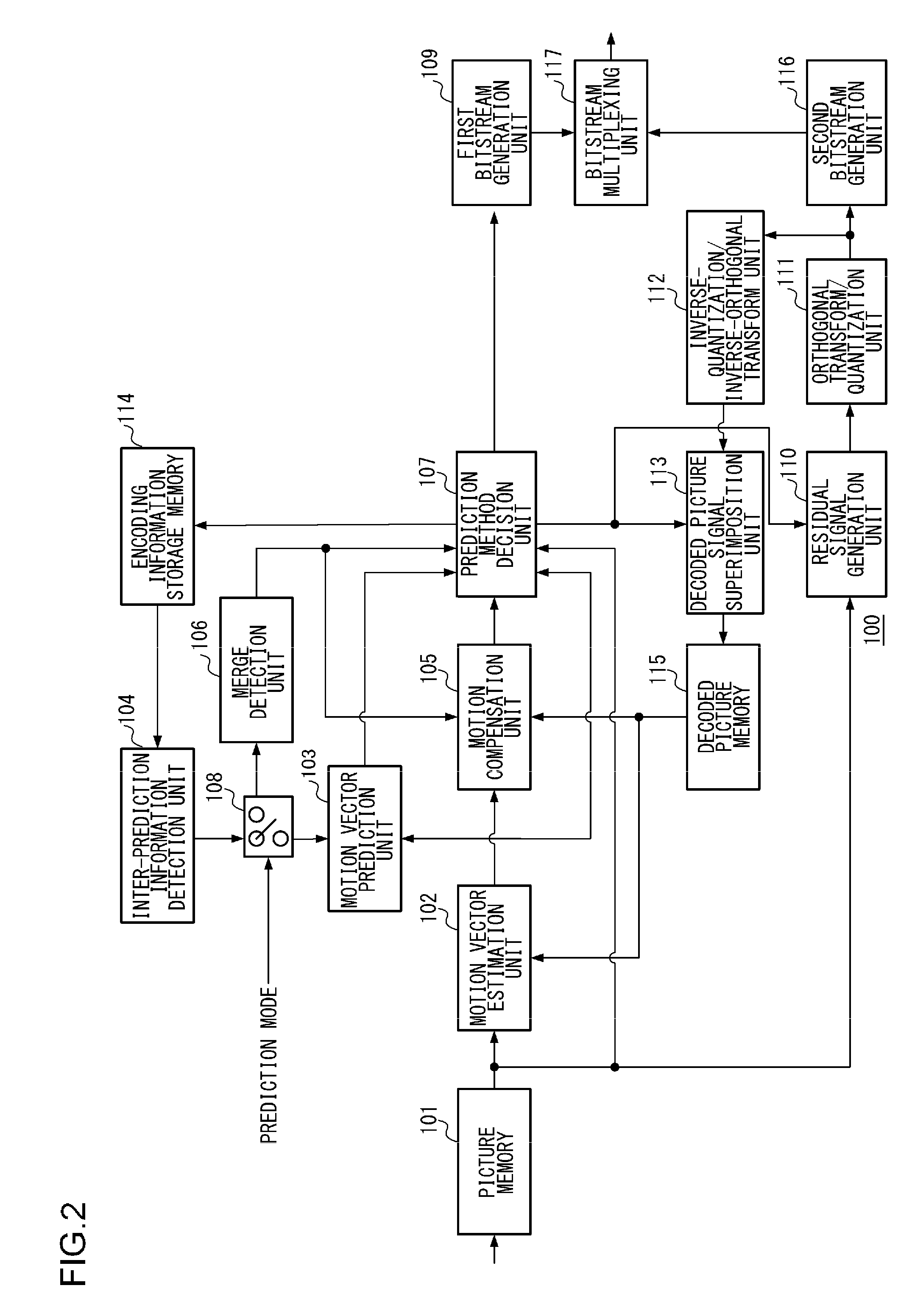
[0160]A description will first be given of the merge detection unit 106 according to the first embodiment shown in FIG. 2 illustrating the configuration of the moving picture coding device 100. FIG. 11 shows the detailed configuration of the merge detection unit 106. The part bounded by the heavy dotted line in FIG. 11 represents the merge detection unit 106 and a description will be given with reference to this drawing. The merge detection unit 106 includes a coding information derivation unit 310, a reference candidate list construction unit 311, an identical information detection unit 312, an output unit 313, and a reference candidate list storage memory 314.

[0161]Initially, the destination of the output of the inter-prediction information detection unit 104 is switched to the merge detection unit 106 according to the prediction mode input to the switch 108 and controlled by the moving picture coding device 100. The coding information of the reference neighboring blocks referred ...

second embodiment

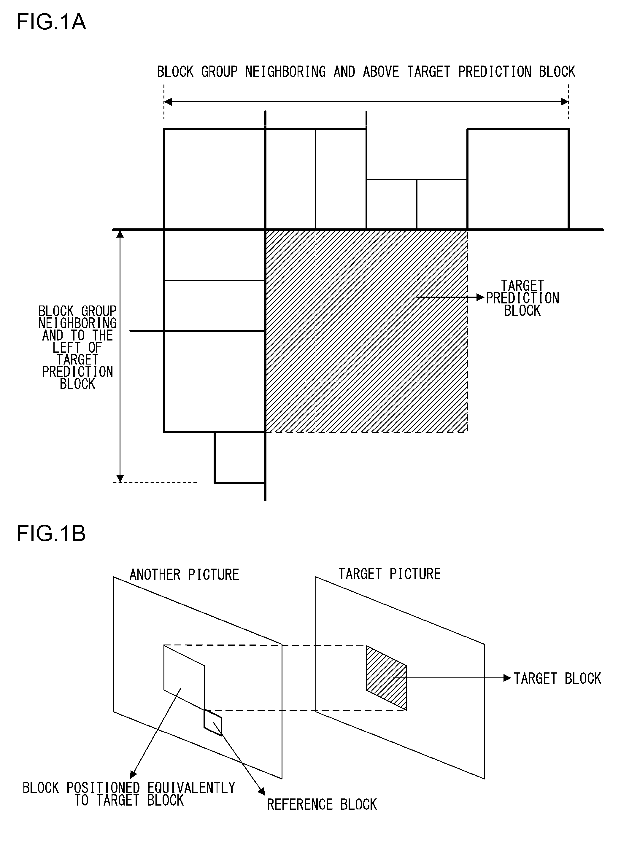
[0244]FIGS. 31A and 31B show arrangements of reference neighboring blocks referred to by the target prediction block according to the second embodiment. Neighboring blocks are denoted by similar symbols as in FIGS. 9A and 9B. The exemplary arrangement of FIG. 31A is used in the following description. According to the second embodiment, the neighboring blocks located in the same picture as the target prediction block are organized into a block group neighboring the target prediction block to the left (A0 and A1 in FIG. 31A) and a block group neighboring above (B0, B1, and C0 in FIG. 31A). One reference neighboring block is selected to represent each block group.

[0245]As in the first embodiment, a decision is made as to whether the neighboring block is available by referring to the prediction mode of the coding information of the neighboring block and the position of the neighboring block. The second embodiment differs in that one representative neighboring block is selected from each...

third embodiment

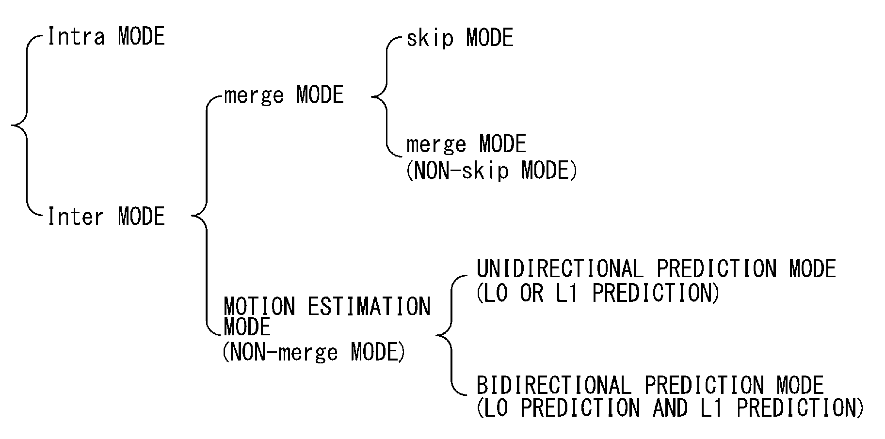
[0301]In the third embodiment, the method of selecting the reference neighboring block is changed according to the prediction mode. A description will be made with reference to the arrangement of neighboring blocks in FIG. 31A. In the merge mode, the coding information of one of six neighboring blocks A0, A1, B0, B1, C0, T is selected as the reference target. In the motion estimation mode, of the six neighboring blocks A0, A1, B0, B1, C0, and T, A0 and A1 are placed in a block group neighboring the target prediction block to the left, and B0, B1, and C are placed in a block group neighboring above. One reference neighboring block is selected to represent each block group. Of the three neighboring blocks including the blocks respectively representing the block group to the left and the block group above and the block T, the coding information of one neighboring block is selected as the reference target. In other words, the method according to the first embodiment is used in the merge...


PUM


Abstract

In a first inter-image prediction mode in which information on a motion vector is used, a first mode detection unit constructs a first candidate list from a plurality of reference block candidates based on a first predetermined order, assigns indices for designating reference block candidates added in the first candidate list, and outputs the indices of the plurality of reference candidate blocks. In a second inter-image prediction mode in which is used a motion vector difference between a motion vector predictor based on information on a motion vector, and a motion vector of a coding target block, a second mode detection unit constructs a second candidate list from a plurality of reference block candidates based on a second predetermined order, assigns indices for designating reference block candidates added in the second candidate list, and outputs the indices of the plurality of reference block candidates and motion vector differences.

Description

BACKGROUND OF THE INVENTION[0001]1. Field of the Invention[0002]The present invention relates to a technology of coding moving pictures, and, more particularly, to an picture coding device, picture coding method, picture coding program, picture decoding device, picture decoding method, and picture decoding program configured to partition a picture into rectangular blocks and estimate and compensate for motion between pictures in units of blocks.[0003]2. Description of the Related Art[0004]In a moving picture coding system as exemplified by MovingPictureCodingExpertsGroup (MPEG), in which a picture is partitioned into rectangular blocks, and motion between pictures is estimated and compensated for in units of blocks, a motion vector is predicted in order to reduce the code size of motion vectors generated in the blocks.[0005]In MPEG-2, the code size is reduced by derivating a difference between a motion vector detected in a given macroblock and a motion vector for an immediately prev...

Claims


Application Information

Patent Timeline
IPC IPC(8): H04N19/51H04N19/583
CPCH04N19/00733H04N19/00684H04N19/103H04N19/105H04N19/119H04N19/139H04N19/159H04N19/176H04N19/184H04N19/46H04N19/51H04N19/513H04N19/52H04N19/70H04N19/109
Inventor NISHITANI, MASAYOSHINAKAMURA, HIROYATAKEHARA, HIDEKIFUKUSHIMA, SHIGERU
Owner JVC KENWOOD CORP A CORP OF JAPAN
Why Eureka
Try Eureka