
Progressive scan video processing

a video processing and video technology, applied in the field of progressive video scanning, can solve the problems of increasing the bandwidth requirement of progressive scanning by a ratio of two bandwidth requirements, affecting the reconstitution of high frequency vertical signal components, and affecting the quality of interlaced signals

Active Publication Date: 2014-08-07
V NOVA INT LTD
View PDF0 Cites 0 Cited by
  • Summary
  • Abstract
  • Description
  • Claims
  • Application Information

AI Technical Summary

Benefits of technology

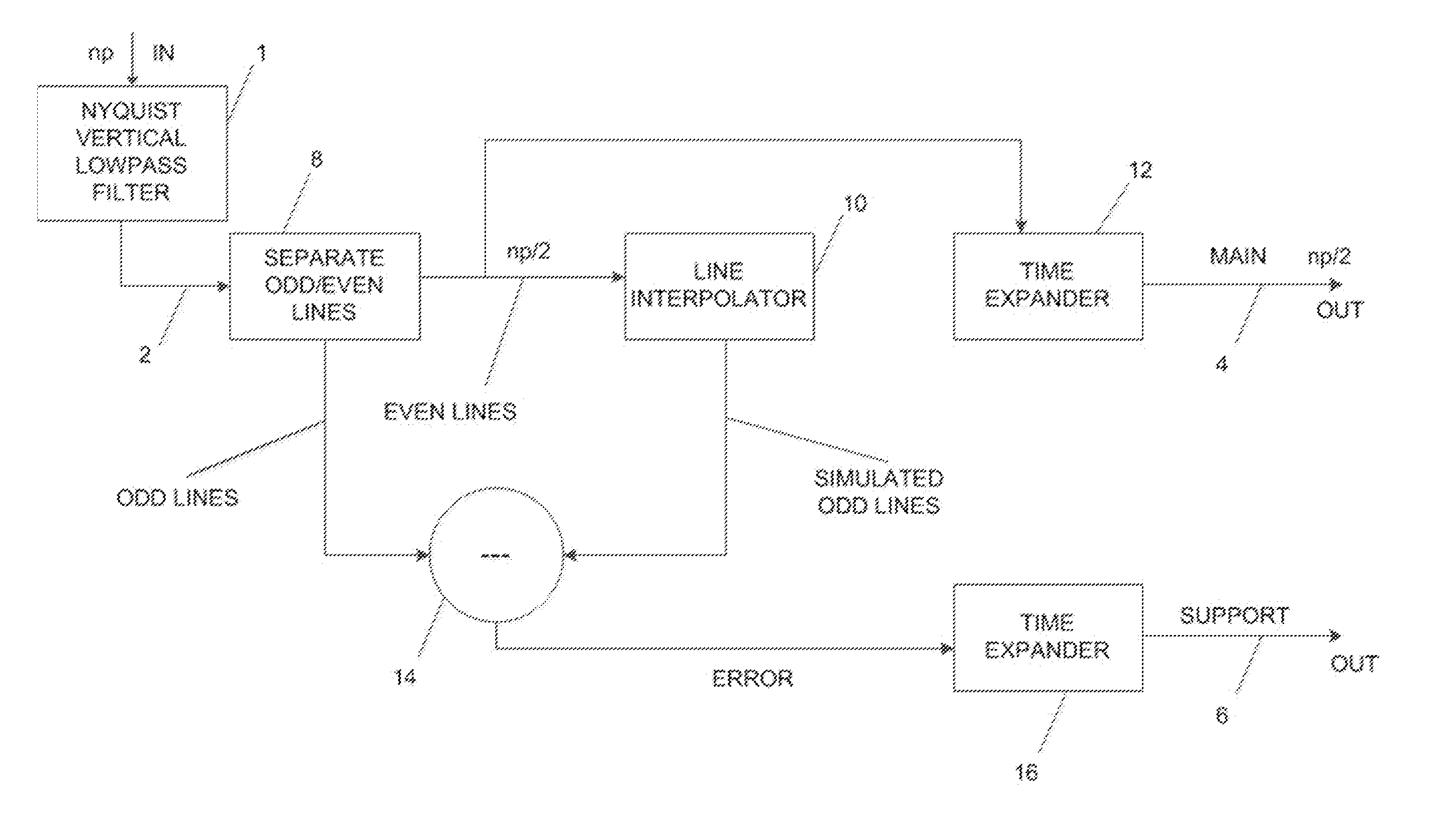
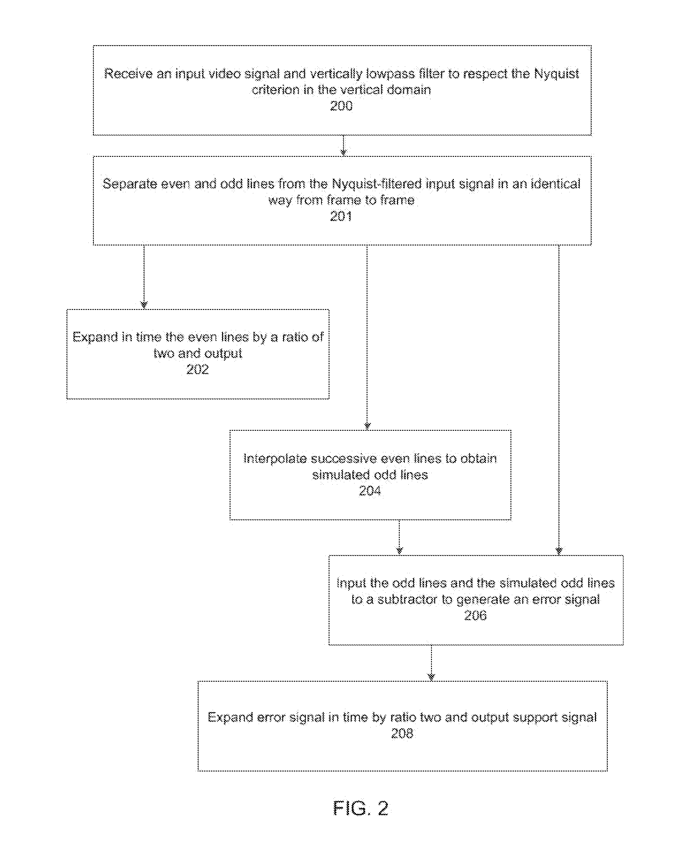
The present invention provides methods for processing progressive scan video signals by using low frequency vertical signal components and an error signal to improve the reconstitution of high frequency vertical signal components. The methods involve separating even and odd scan lines, deriving a simulation of the odd scan lines, subtracting the simulation from the even scan lines to obtain an error signal, deriving from the even scan lines a simulation of the odd scan lines, improving the reconstitution of the odd scan lines by using the error signal, and combining the improved reconstitution of the odd scan lines and the low frequency vertical components of the progressive scan video signal to provide a full bandwidth of the video signal. The invention also provides a method for separating high-frequency vertical signal components from low-frequency vertical signal components and using the support signal to enhance the vertical domain resolution of the video signal.

Problems solved by technology

In these cases, interlaced signals have to be de-interlaced, which is costly and difficult.
The main disadvantage of progressive scan is an increase by a ratio of two of bandwidth requirements, as compared to an interlaced standard having the same field rate as the comparable progressive scan standard.
The requirements for bandwidth are increasing daily, and the available bandwidth provided by present communication channels is limited.
Furthermore, interlace standards, which in the past employed analog transmission, reduced the bandwidth requirements by two at the cost of image quality (artifacts).
Interlacing does not present such an advantage in compression systems, and is not computer-friendly.

Method used


Image

  • Progressive scan video processing
  • Progressive scan video processing
  • Progressive scan video processing

Examples


Embodiment Construction

[0029]The exemplary embodiments relate to methods, devices and systems for processing a progressive scan video signal and a modified progressive scan video signal. The following description is presented to enable one of ordinary skill in the art to make and use the invention and is provided in the context of a patent application and its requirements. Various modifications to the exemplary embodiments and the generic principles and features described herein are readily apparent. The exemplary embodiments are mainly described in terms of particular methods and systems provided in particular implementations. However, the methods and systems will operate effectively in other implementations. Phrases such as “exemplary embodiment”, “one embodiment” and “another embodiment” may refer to the same or different embodiments. The embodiments are described with respect to systems and / or devices having certain components. However, the systems and / or devices may include more or fewer components t...


PUM


Abstract

A method and system for separating even and odd lines in a progressive video signal comprises generating from the even lines simulated odd lines, comparing the simulated odd lines with the original odd lines to obtain a support signal, and transmitting the even lines and the support signal in order to reconstitute the full picture. Alternatively, separating odd and even lines may be replaced by separating high- and low-frequency vertical signal components, generating from the low-frequency vertical signal components simulated high-frequency vertical signal components, comparing the simulated high-frequency vertical signal components with the original high-frequency signal components to obtain a support signal.

Description

CROSS-REFERENCE TO RELATED APPLICATIONS[0001]This application claims the benefit of provisional Patent Application Ser. No. 61 / 760,275, filed Feb. 4, 2013, and is assigned to the Assignee of the present application and incorporated herein by reference.BACKGROUND[0002]In progressive video scanning, successive scanning lines are vertically aligned from frame to frame. For example, in the 1080p / 60 standard (1080 scanning lines per frame, 60 frames per second), line 1 of frame 2 is scanned at the same vertical location as is line 1 of frame 1, and so are lines 1 of frames 3, 4, etc. For interlaced video, line 1 of field 2 is vertically located between line 1 and line 2 of field 1, and so is line 1 of field 4, while line 1 of field 3 is vertically coincident with line 1 of field 1.[0003]An interlaced signal is composed of a succession of even and odd fields, two successive fields making a frame. For example, in the 1080i / 60 standard (1080 lines interlaced, 60 fields per second), each fie...

Claims


Application Information

Patent Timeline
IPC IPC(8): H04N7/26
CPCH04N19/00854H04N19/593H04N19/65
Inventor FAROUDJA, YVES
Owner V NOVA INT LTD
Learn More