Individual inlet guide vane control for tip turbine engine

Active Publication Date: 2014-08-07
RAYTHEON TECH CORP
View PDF1 Cites 9 Cited by
  • Summary
  • Abstract
  • Description
  • Claims
  • Application Information

AI Technical Summary

Benefits of technology

[0008]With independent control of the variable inlet guide vanes, distortion at the inlet to the bypass fan and/or the inlet to the compressor is reduced, thereby improving the stability of the turbine engine. The independently variable inlet guide vanes can be used in tip turbine engine

Problems solved by technology

The axial flow relationship results in a relatively complicated elongated engine structure of considerable length relative to the engine diameter.
This elongated shape

Method used


Image

  • Individual inlet guide vane control for tip turbine engine
  • Individual inlet guide vane control for tip turbine engine
  • Individual inlet guide vane control for tip turbine engine

Examples


Embodiment Construction

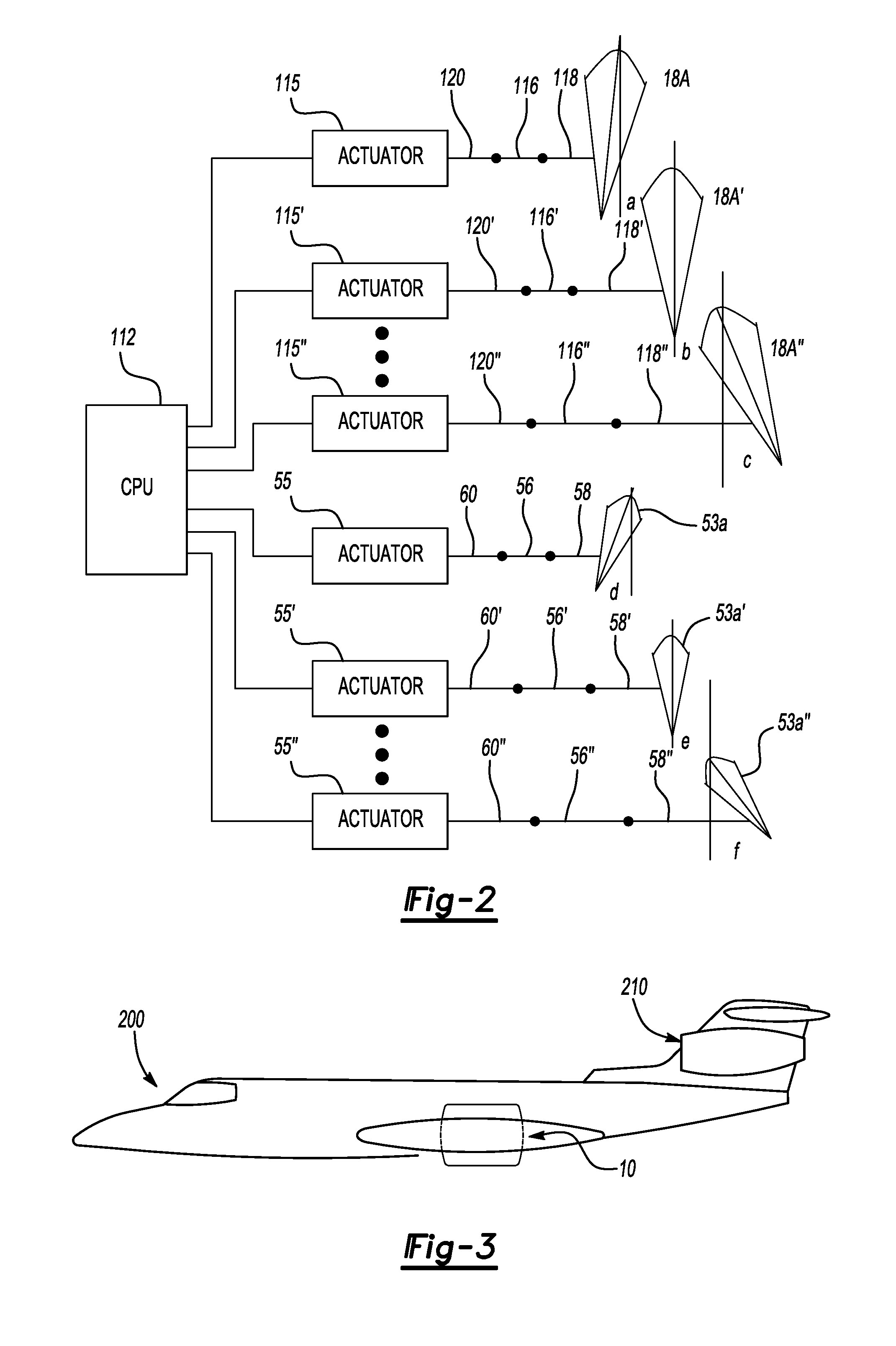
[0015]FIG. 1 is a partial sectional view of a tip turbine engine (TTE) type gas turbine engine 10 taken along an engine centerline A. Although the turbine engine 10 is shown horizontally, the turbine engine 10 could be mounted at any orientation, and as explained above, vertical orientations would experience particular benefits from the present invention. The turbine engine 10 includes an outer housing 12, a rotationally fixed static outer support structure 14 and a rotationally fixed static inner support structure 16. A plurality of fan inlet guide vanes 18 are mounted between the static outer support structure 14 and the static inner support structure 16. Each fan inlet guide vane 18 includes a variable flap 18A.

[0016]A nosecone 20 may be located along the engine centerline A to improve airflow into an axial compressor 22, which is mounted about the engine centerline A behind the nosecone 20. The nosecone 20 might not be used in vertical installations.

[0017]A fan-turbine rotor ass...


PUM


Abstract

A tip turbine engine according to the present invention includes a plurality of independently variable inlet guide vanes for the fan and/or for the compressor. An actuator is operatively coupled to each of the flaps, such that each actuator can selectively vary the flap of its associated inlet guide vane. In one embodiment, the inlet guide vanes each include a pivotably mounted flap that is variable independently of the flaps of at least some of the other inlet guide vanes. In another embodiment, the inlet guide vanes each include at least one fluid outlet or nozzle directing pressurized air, as controlled by the associated actuator, to control inlet distortion.

Description

CROSS REFERENCE TO RELATED APPLICATIONS[0001]This is a divisional application of U.S. patent application Ser. No. 11 / 719,868 dated May 22, 2007.BACKGROUND OF THE INVENTION[0002]The present invention relates to turbine engines, and more particularly to individually controlled inlet guide vanes for a tip turbine engine.[0003]An aircraft gas turbine engine of the conventional turbofan type generally includes a forward bypass fan, a low pressure compressor, a middle core engine, and an aft low pressure turbine, all located along a common longitudinal axis. A high pressure compressor and a high pressure turbine of the core engine are interconnected by a high spool shaft. The high pressure compressor is rotatably driven to compress air entering the core engine to a relatively high pressure. This high pressure air is then mixed with fuel in a combustor, where it is ignited to form a high energy gas stream. The gas stream flows axially aft to rotatably drive the high pressure turbine, which...

Claims


Application Information

Patent Timeline
IPC IPC(8): F01D17/16
CPCF01D17/16F05D2220/327F02C9/20F02K3/06Y10S415/914F01D17/162F02C3/073
Inventor NORDEEN, CRAIG A.NORRIS, JAMES W.
Owner RAYTHEON TECH CORP
Why Eureka
Try Eureka