
Portable Terminal Device and Program

Inactive Publication Date: 2014-08-07
NEC CORP
View PDF3 Cites 36 Cited by
  • Summary
  • Abstract
  • Description
  • Claims
  • Application Information

AI Technical Summary

Benefits of technology

The present invention is about a portable device that can save power by limiting the supply of power. However, this device doesn't require a mechanical button to restore normal power mode. Instead, the device allows the user to partially remove the power limitation before using it, making it more practical and user-friendly.

Problems solved by technology

In recent years, in the case of a portable terminal device such as a multifunctional portable telephone referred to as a smart phone, since a touch panel is mounted thereon as an operation input device, the number of mechanical push buttons is extremely limited, and many of them are provided with only the power-supply button for use in turning ON / OFF the power supply.

Method used


Image

  • Portable Terminal Device and Program
  • Portable Terminal Device and Program
  • Portable Terminal Device and Program

Examples


first embodiment

[0030]First, referring to FIG. 1 to FIG. 5, the following description will discuss the first embodiment of the present invention.

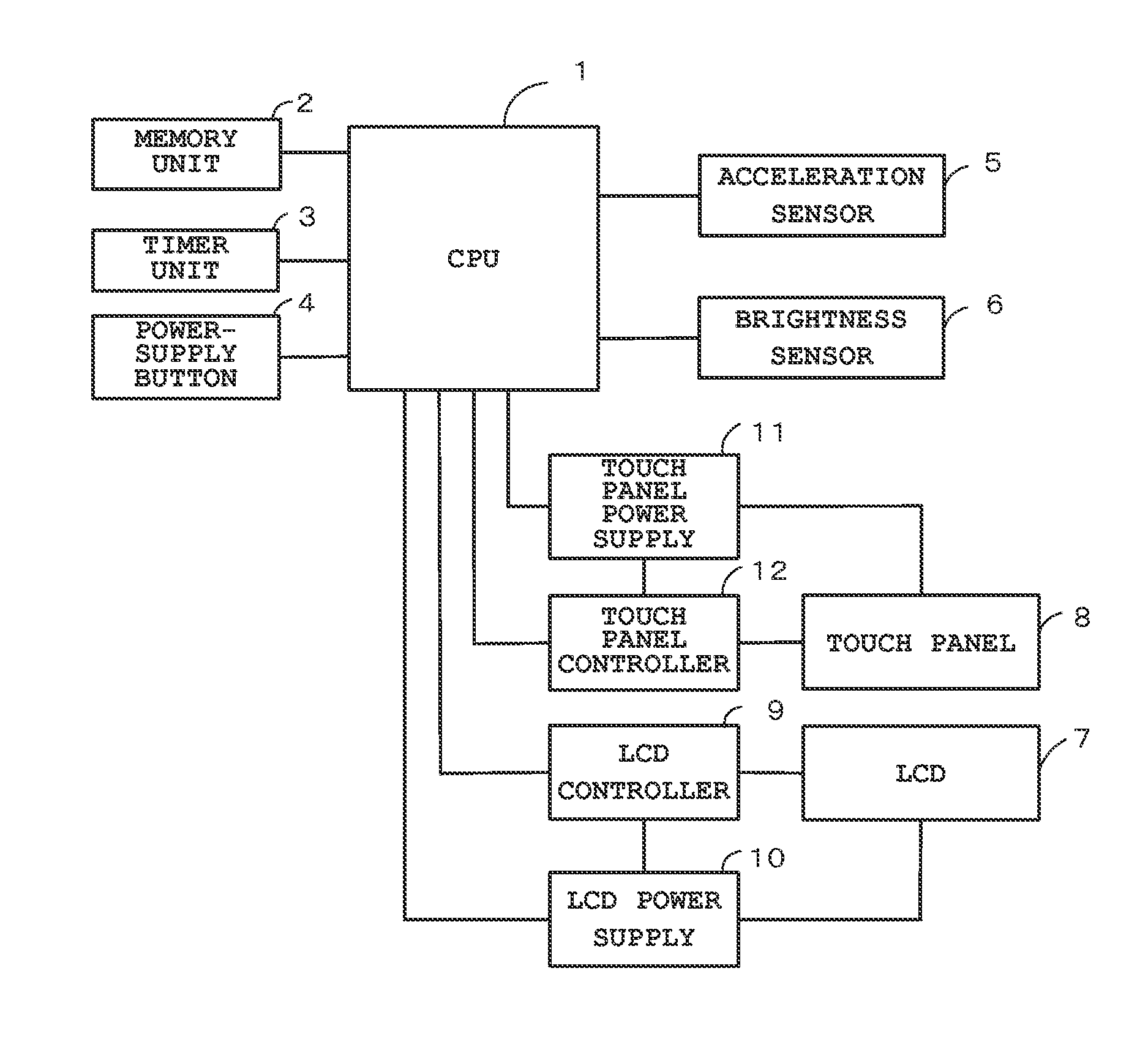
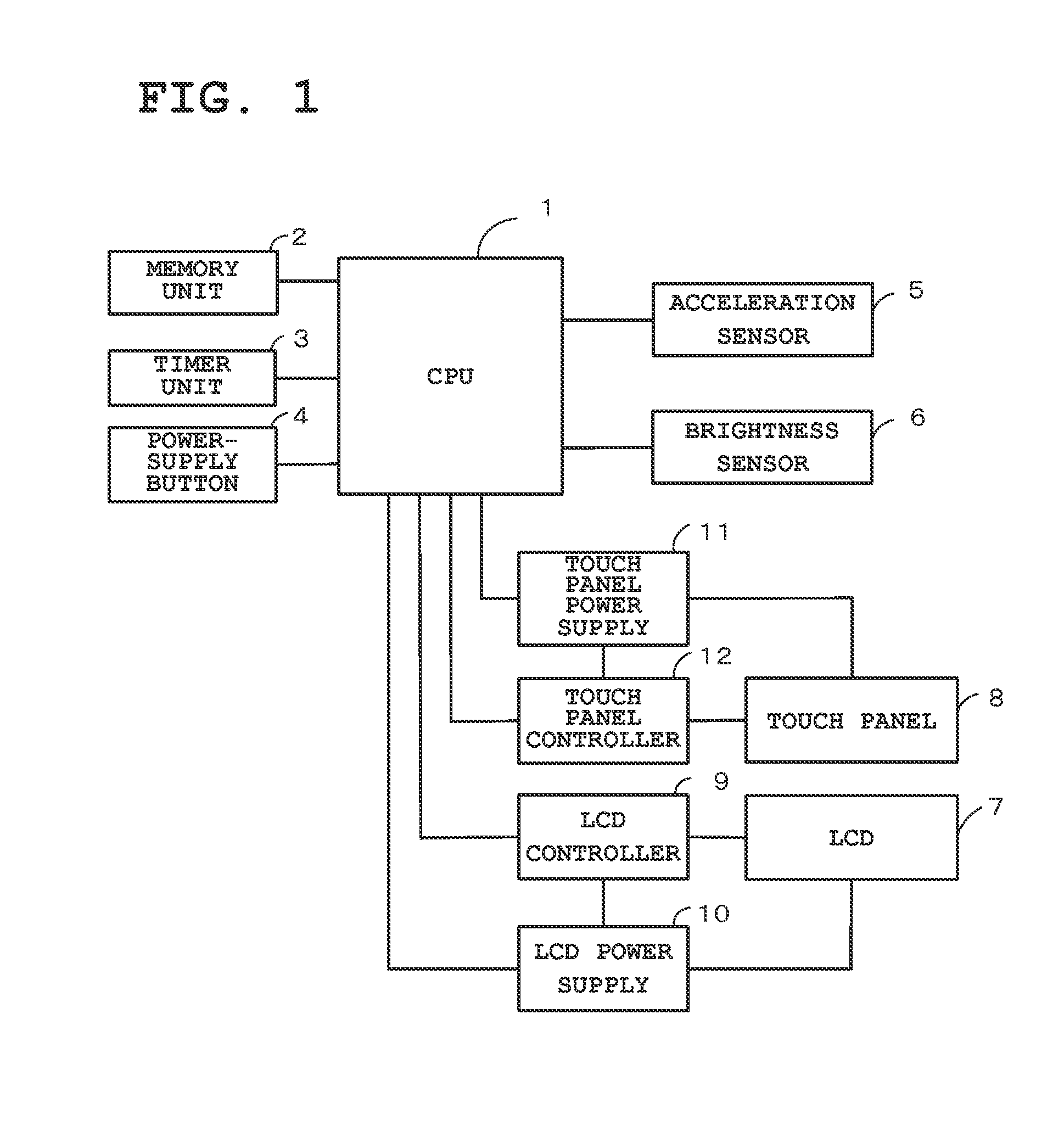
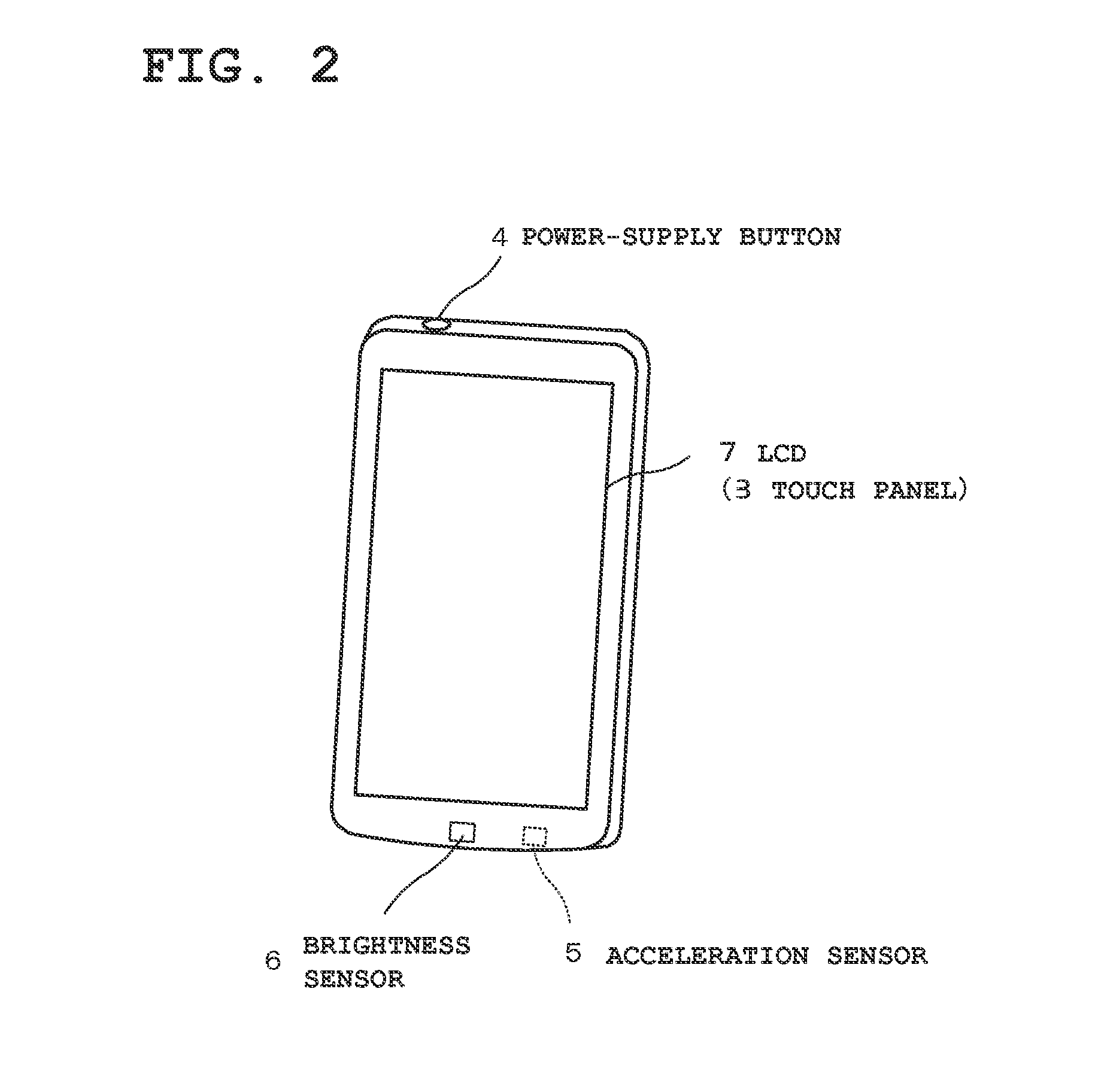
[0031]FIG. 1 is a block diagram that shows a basic configuration of a portable telephone of a multifunctional type referred to as a smart phone that is applied as a portable terminal device. This portable telephone (smart phone) is equipped with functions of various kinds, such as a voice call function, an e-mail function and the Internet access function (Web access function), and is provided with a radio communication unit, a call-use speaker, a call-use microphone, and the like, although illustrations thereof are omitted from FIG. 1. Moreover, when connected to another portable telephone through a radio communication network (not shown), the portable telephone is brought into a communicable state with another portable telephone, or transmittable and receivable states of electronic mails therewith. Furthermore, when connected to the Internet (not shown) t...

embodiment 2

[0059]Referring to FIG. 6 and FIG. 7, the following description will discuss a second embodiment of the present invention.

[0060]In the above-mentioned first embodiment, the present invention is applied to the touch panel 8 as a predetermined peripheral device in which the power supply is limited in the power conservation mode, and in the state where the power supply to the touch panel 8 is limited, the limit on the supply of power to the touch panel 8 is removed in accordance with detection results of the acceleration sensor 5 and the brightness sensor 6; however, in the second embodiment, the present invention is applied to a camera (image capture device) as the predetermined peripheral device in which the power supply is limited in the power conservation mode, and in the state where the power supply to the camera is limited, the limit on the supply of power to the camera is removed in accordance with detection results of the acceleration sensor 5 and the brightness sensor 6. In th...


PUM


Abstract

The present invention is to enable a portable telephone capable of switching to a power conservation state so as to reduce power consumption by limiting the supply of power, in which the limit on the supply of power can be partially removed immediately before the portable telephone is used, without the necessity of cancelling the power conservation mode through a mechanical button operation to restore the normal power state. In the case while the supply of power to a predetermined peripheral device (touch panel) is being limited by a power conservation mode, an acceleration sensor detects vibrations applied to the portable telephone as a first state and a brightness sensor detects the ambient brightness of the portable telephone as a second state, a CPU removes the limit on the supply of power to the predetermined peripheral device on the basis of the first state and the second state.

Description

TECHNICAL FIELD[0001]The present invention relates to a portable terminal device capable of reducing power consumption by limiting the supply of power and a program of such a device.BACKGROUND ART[0002]In recent years, in the case of a portable terminal device such as a multifunctional portable telephone referred to as a smart phone, since a touch panel is mounted thereon as an operation input device, the number of mechanical push buttons is extremely limited, and many of them are provided with only the power-supply button for use in turning ON / OFF the power supply. Moreover, as a method for reducing power consumption, such a multifunctional portable terminal device uses a power conservation method in which switching is made between a normal power state (normal power mode) in which the power supply is not limited and a power conservation state (power conservation mode) in which the power consumption is reduced by limiting the power supply. In this case, the switching from the normal...

Claims


Application Information

Patent Timeline
IPC IPC(8): H04W52/02G06F3/041
CPCH04W52/0254G06F2203/04106G06F3/041H04M2250/12H04M2250/22H04W52/027G06F1/3206G06F1/3231G06F1/3287Y02D10/00Y02D30/70
Inventor OGURI, SHINJI
Owner NEC CORP
Learn More