Crane control

a crane and control technology, applied in the field of cranes, can solve the problems of sensor powering, sensor located near the hook is rather vulnerable to external impacts, and the deviation angle of the measured rope is not accurate,

Active Publication Date: 2014-08-14
KONECRANES GLOBAL
View PDF4 Cites 67 Cited by
  • Summary
  • Abstract
  • Description
  • Claims
  • Application Information

AI Technical Summary

Benefits of technology

[0006]The invention is based on measuring a rope angle deflection by means of an angle sensor located at or adjacent to a trolley, and correcting, by compensating an error caused by a speed change, the rope angle feedback information thus obtained, and using the corrected rope angle feedback information to provide control information, like movement instructions.
[0007]An advantage provided by the compensating is that the error caused by the acceleration, for example, is corrected and erroneous angle information, and thereby erroneous control information, are avoided. In other words, the corrected rope angle feedback information gives the real rope angle in real time with sufficient accuracy even when the speed of the crane changes. Thus the crane control is based on real, correct information all the time. Brief description of the drawings

Problems solved by technology

A drawback of connecting a sensor in a hook to a controller in the crane requires either a long wiring, which is vulnerable to entanglement, or a wireless transmitter in the sensor and a corresponding receiver in the controller, and the powering of the sensor is also problematic.
Another drawback is that a sensor located near the hook is rather vulnerable to external impacts, such as an accidental collision with the load when the load is attached to the hook.
A problem with the solution in WO 2009 / 138329 is that it ignores the fact that, especially when the rope deviation angle is measured by a sensor / sensors positioned in a vicinity of the rope anchorage, an acceleration or deceleration of the crane causes an error to the measured rope deviation angle.

Method used


Image

  • Crane control
  • Crane control
  • Crane control

Examples


Embodiment Construction

[0019]The following embodiments are exemplary. Although the specification may refer to “an”, “one”, or “some” embodiment(s) in several locations, this does not necessarily mean that each such reference is to the same embodiment(s), or that the feature only applies to a single embodiment. Single features of different embodiments may also be combined to provide other embodiments.

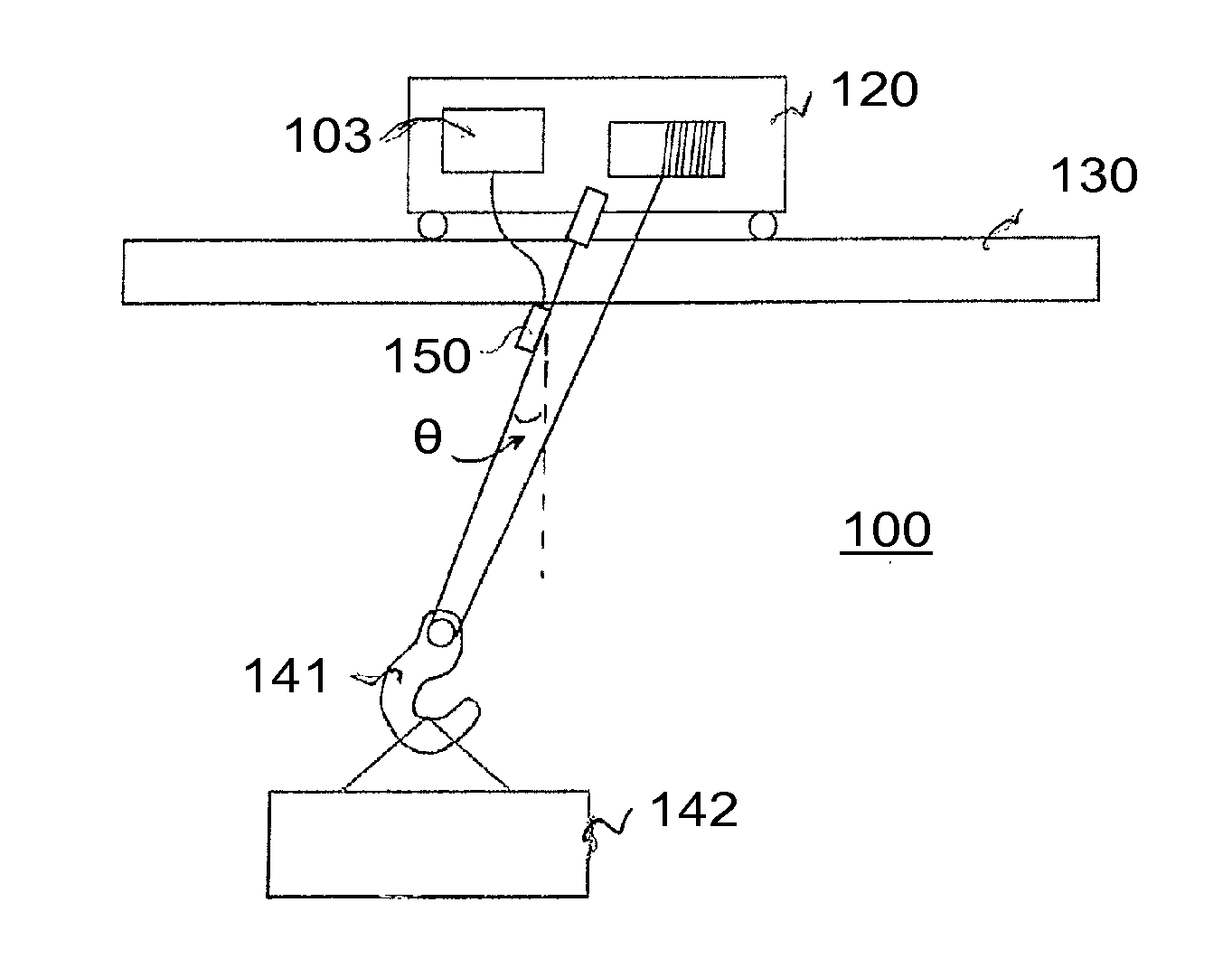
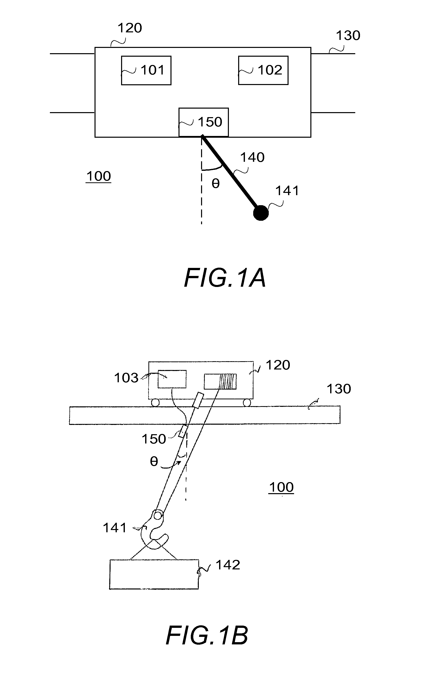
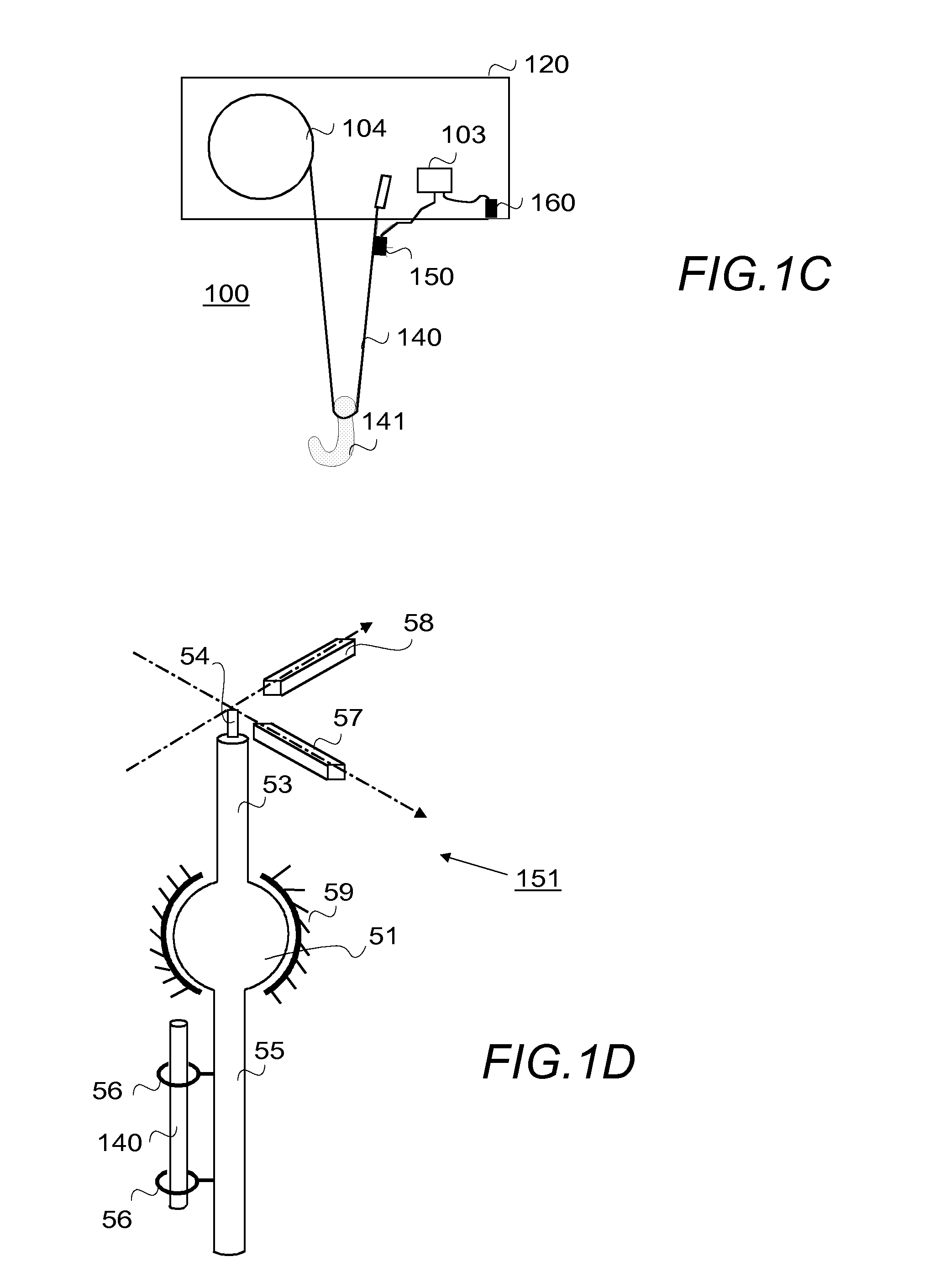
[0020]The present invention is applicable to any crane, or crane arrangement in which a rope or ropes or corresponding means are used in hoisting, and the rope is mounted to a movable apparatus that is able to move at least along one axis. In the following, different examples and embodiments are described using an overhead bridge crane as an example without restricting the embodiments to such a crane, however. Other examples include standard and heavy duty cranes, such as a gantry crane, tower crane, slewing jib crane, ship-to-shore (STS) container crane, offshore crane, crane with several hoists (crane having...


PUM


Abstract

To facilitate the use of a crane, an angle feedback information on a rope angle (θ) of the crane is received, the angle feedback information being measured by means of a sensor at or adjacent to a trolley; and the angle feedback information is corrected by compensating an error caused by a speed change, and processed to provide movement instructions or other control information relating to the crane on the basis of real-time corrected angle information.

Description

FIELD[0001]The present invention relates to cranes, and especially to utilizing a rope angle measurement for a crane control.BACKGROUND ART[0002]Cranes are apparatuses which are intended for transferring loads, both in the open air and in closed environments. In manufacturing factories a crane is typically a bridge crane, movable along tracks by means of a bridge moving in the direction of the tracks and one or more trolleys moving along the bridge in the direction substantially perpendicular to the direction of the tracks, on which trolleys with one or more ropes, or corresponding hoisting means, such as belts and chains, are mounted. Although in an ideal situation each rope is vertical or almost vertical so that the load is directly under the trolley, in real life the ropes every now and then deviate from the ideal situation, and a need to know the actual rope angle, i.e. how much the rope has deviated, arises.[0003]Several methods for finding out a deflection angle of a load are ...

Claims


Application Information

Patent Timeline
Patent Type & Authority Applications(United States)
IPC IPC(8): B66C13/06
CPCB66C13/06B66C13/46G01C9/08G01B5/24G01C9/00
Inventor ERIKSSON, LASSEYLA-SOININMAKI, HARRISALOMAKI, JANNE
Owner KONECRANES GLOBAL
Why Eureka
Try Eureka