Angular resin container and blow molding die

a technology of resin container and blow molding die, which is applied in the field of resin-made containers, can solve the problems of easy deformation of the container, reduced strength of the container, and recesses towards the inside of the container, and achieves excellent appearance in respect of luster, transparency, and easy obtaining

Active Publication Date: 2014-08-14
TOYO SEIKAN GRP HLDG LTD
View PDF1 Cites 0 Cited by
  • Summary
  • Abstract
  • Description
  • Claims
  • Application Information

AI Technical Summary

Benefits of technology

[0013]According to the angular resin container of the present invention, an angular resin container which, while being thin, has excellent appearance in respect of luster, transparency or the like can be provided.
[0014]Further, according to the blow molding die for the angular molding resin container of the present invention, without conducting a surface treatment to allow the cavity surface to be rough after cutting, it is possible to obtain easily by molding an angular resin container that is thin and has excellent appearance in respect of luster, transparency or the like by significantly decreasing mold release resistance at the time of releasing from the cavity surface of the blow molding die the angular resin container after the biaxial stretch blow molding, whereby the container is prevented from being deformed.

Problems solved by technology

However, if the resin container becomes thin, the strength of the container is inevitably decreased, and as a result, the container tends to be deformed easily.
As a result, as shown in FIG. 4, a problem arises that a corner surface part 42 that has been released from the mold earlier than the side wall part 41 acts such that it deforms in the form of a recess towards the inside of the container.
If the cavity surface of the blow molding die is a mirror-finished surface, a problem arises that air remains between the container and the cavity surface, and as a result, pockmark-like air pool marks are formed on the surface of the container, resulting in deterioration of the appearance.

Method used


Image

  • Angular resin container and blow molding die
  • Angular resin container and blow molding die
  • Angular resin container and blow molding die

Examples


Embodiment Construction

[0019]Hereinafter, a preferable embodiment of the present invention will be explained with reference to the drawings.

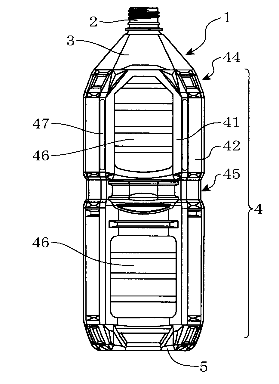
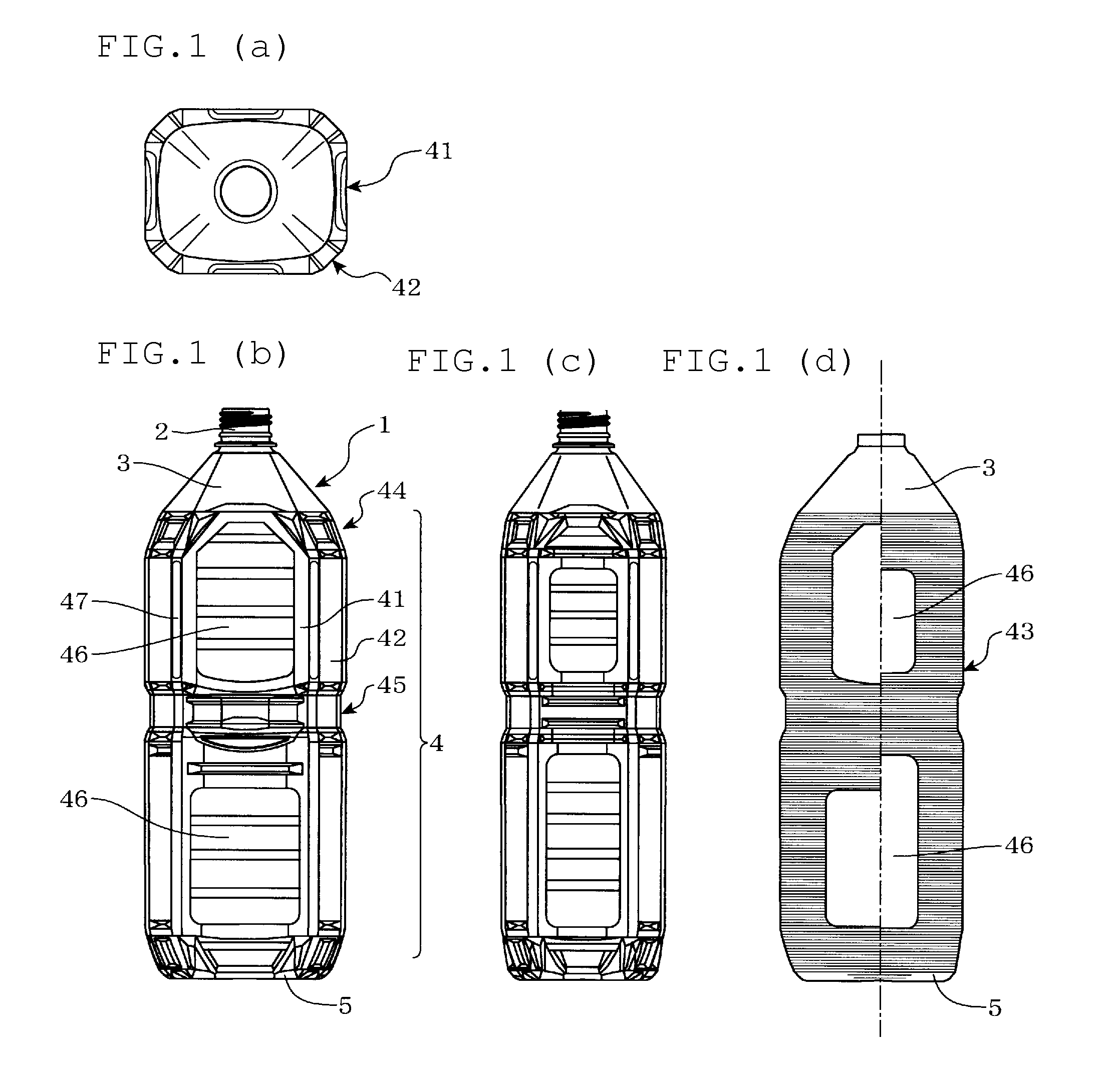
[0020]In this embodiment, for example, an angular resin container 1 is a container obtained by subjecting a bottomed cylindrical preform that is made of a thermoplastic resin and is produced by known injection molding or compression molding to biaxial stretch blow molding. The container 1 has a mouth part 2, a shoulder part 3, a body part 4 and a bottom part 5. The shape of a lateral cross section that orthogonally crosses the height direction of the body part is angular, and a rectangular-shaped inner pressure-adjusting panel 46 is formed on a side wall part 41 of the body part 4.

[0021]As the thermoplastic resin that constitutes the angular resin container 1, an arbitral resin can be used as long as it can be subjected to biaxial stretch blow molding. As specific examples, thermoplastic polyesters such as polyethylene terephthalate, polybutylene terephthalate, polyet...


PUM

PropertyMeasurementUnit
depthaaaaaaaaaa
thicknessaaaaaaaaaa
distanceaaaaaaaaaa

Abstract

Provided are an angular resin container, which while being thin, retains excellent appearance in respect of luster, transparency or the like, as well as a blow molding die for subjecting the container to biaxial stretch blow molding. Biaxial stretch blow molding is conducted with a blow molding die having a scallop height for the surface of the blow molding die, that corresponds to the side wall part of the body part of the angular resin container, of 3 to 30 μm, thereby to obtain an angular resin container having a thickness of the body part of 0.5 mm or less and in which a horizontally-directed processed part having a depth of 3 to 30 μm is formed on the outer surface of the side wall part of the body part.

Description

TECHNICAL FIELD[0001]The present invention relates to a resin-made container having an angular cross section (hereinafter referred to as the “angular resin container”) and a blow molding die for biaxial stretch blow molding of the angular resin container. In particular, the present invention relates to an angular resin container in the shape of a bottle and has heat resistance, and a blow molding die for biaxial stretch blow molding of the angular resin container.BACKGROUND ART[0002]Conventionally, a resin container in the shape of a bottle obtained by subjecting a polyester resin such as polyethylene terephthalate to injection molding or compression molding to form a preform, and then molding the preform in the shape of a bottle by the biaxial stretch blow molding has generally been used in wide ranges of fields as a container for beverages that accommodate various types of beverages.[0003]In a blow molding die used in the biaxial stretch blow molding, a space (hereinafter referred...

Claims


Application Information

Patent Timeline
Patent Type & Authority Applications(United States)
IPC IPC(8): B65D1/40B29C49/28
CPCB29C49/28B65D1/40B29C49/08B29C49/48B65D1/0207B65D2501/0081B29L2031/7158B29C49/06B29K2905/02B29C2049/4882B29C49/0685B29C2949/0715
Inventor MIURA, MASAKI
Owner TOYO SEIKAN GRP HLDG LTD
Why Eureka
Try Eureka