

Surface acoustic wave device
a surface acoustic wave and wave technology, applied in piezoelectric/electrostrictive/magnetostrictive devices, piezoelectric/electrostriction/magnetostriction machines, electrical equipment, etc., can solve the problems of increased cost, increased propagation loss, increased size of surface acoustic wave devices, etc., to achieve small propagation loss and high acoustic velocity
- Summary
- Abstract
- Description
- Claims
- Application Information
AI Technical Summary
Benefits of technology
Problems solved by technology
Method used
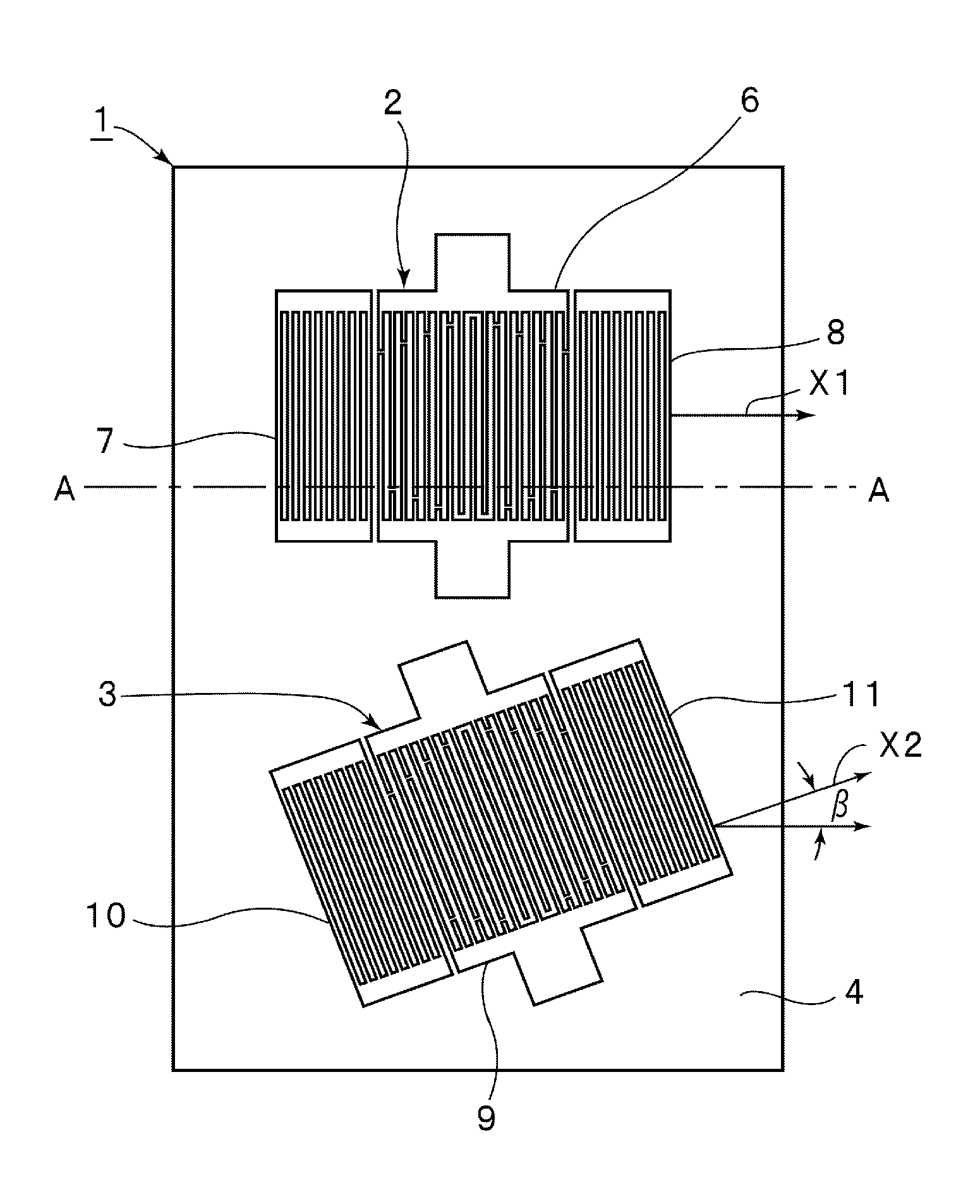
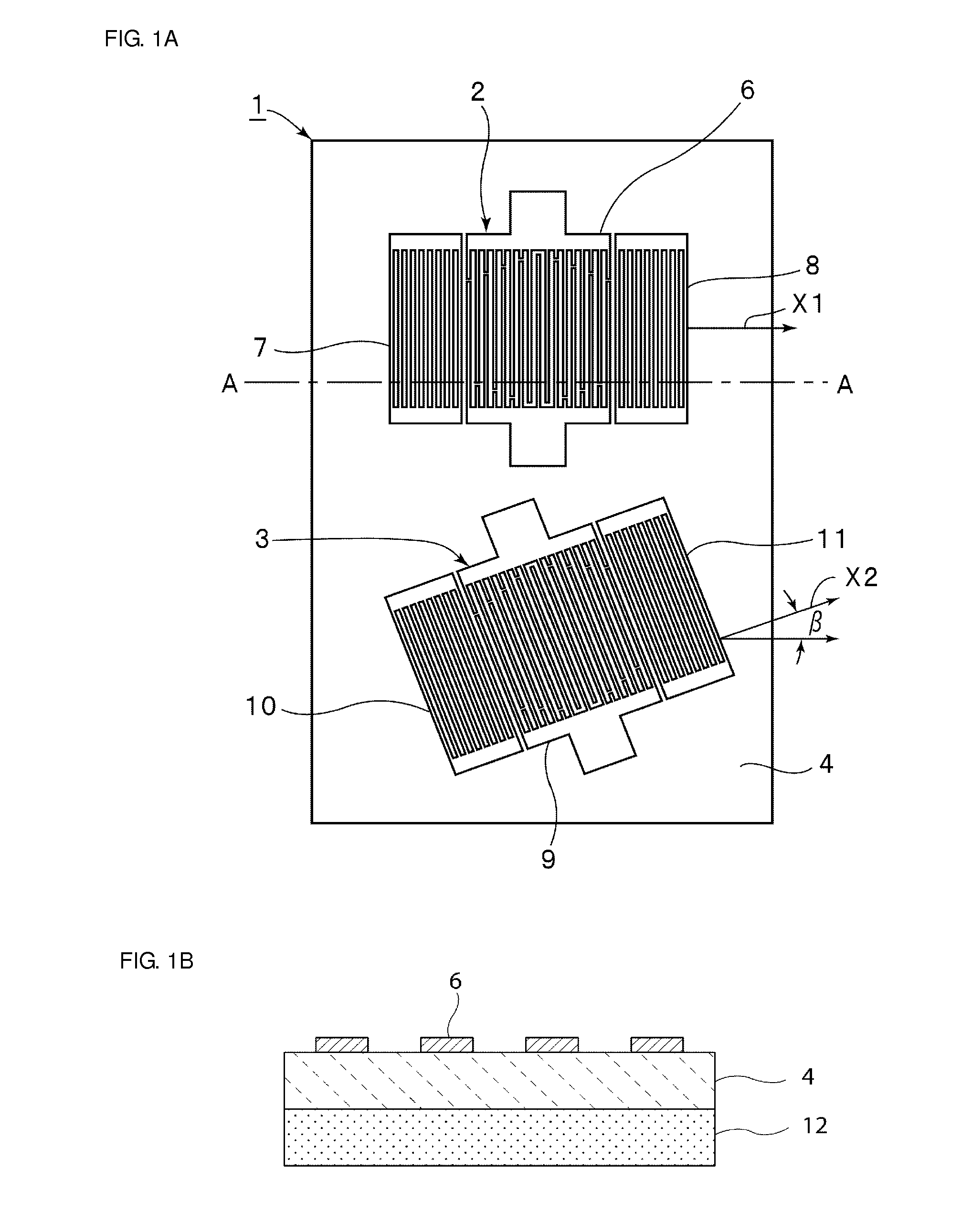
Image

Examples
example 1
Specifications of EXAMPLE 1
[0067]Al(0.08) / LT(0.5) / SiN(2.0) Euler Angles (φ, θ, ψ) of LT=(0 to 30, 0 to 180, 0 to 180)
[0068]Unit of film thickness of each of the electrode and the piezoelectric body: wavelength [λ] Wavelength: 2 μm
[0069]Including the confinement layer
Specifications of COMPARATIVE EXAMPLE 1
[0070]Al(0.08) / LT(200) Euler Angles (φ, θ, ψ) of LT=(0, 128.5, −15 to 15)
[0071]Unit of film thickness of each of the electrode and the piezoelectric body: wavelength [λ] Wavelength: 2 μm
[0072]Including no confinement layer
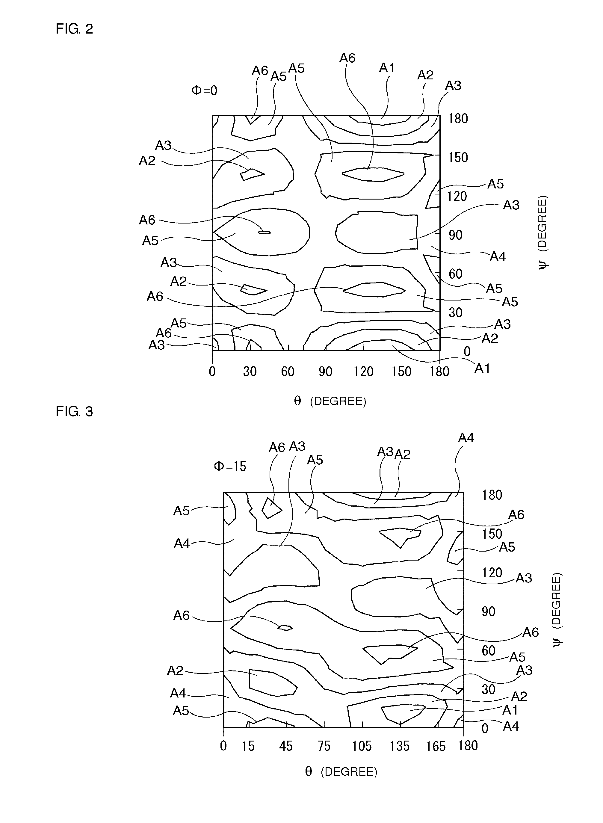
[0073]In EXAMPLE 1 and COMPARATIVE EXAMPLE 1, the propagation loss was measured while the propagation azimuth was changed. As a result, in the case using LiTaO3 having Euler Angles (0°, θ, ψ), an energy concentration ratio of the leaky propagation surface acoustic wave was 100% even when θ was changed in order of 0°, 15°, 30°, 45°, 60°, 75°, 90°, 105°, 120°, 135°, 150°, 165° and 180°, and ψ was changed in order 0°, 30°, 60°, 90°, 120°, 150° and 180°. Thus, no leaka...
PUM
 Abstract
Description
Claims
Application Information