Mixed-mode cavity filter

a cavity filter and mixed-mode technology, applied in the field of cavity filters, can solve the problems of high loss, large size, and higher cost, and achieve the effects of low loss, light weight, and small siz

Active Publication Date: 2014-08-14
ACE TECH
View PDF3 Cites 7 Cited by
  • Summary
  • Abstract
  • Description
  • Claims
  • Application Information

AI Technical Summary

Benefits of technology

[0018]A mixed-mode filter according to an embodiment of the inventi...

Problems solved by technology

Dielectric resonators can provide low insertion loss properties, but relatively larger sizes and higher costs may b...

Method used


Image

  • Mixed-mode cavity filter
  • Mixed-mode cavity filter
  • Mixed-mode cavity filter

Examples


Embodiment Construction

[0029]As the present invention allows for various changes and numerous embodiments, particular embodiments will be illustrated in the drawings and described in detail in the written description. However, this is not intended to limit the present invention to particular modes of practice, and it is to be appreciated that all changes, equivalents, and substitutes that do not depart from the spirit and technical scope of the present invention are encompassed in the present invention. In describing the drawings, like reference numerals are used for like elements.

[0030]Certain embodiments of the invention will be described below in more detail with reference to the accompanying drawings.

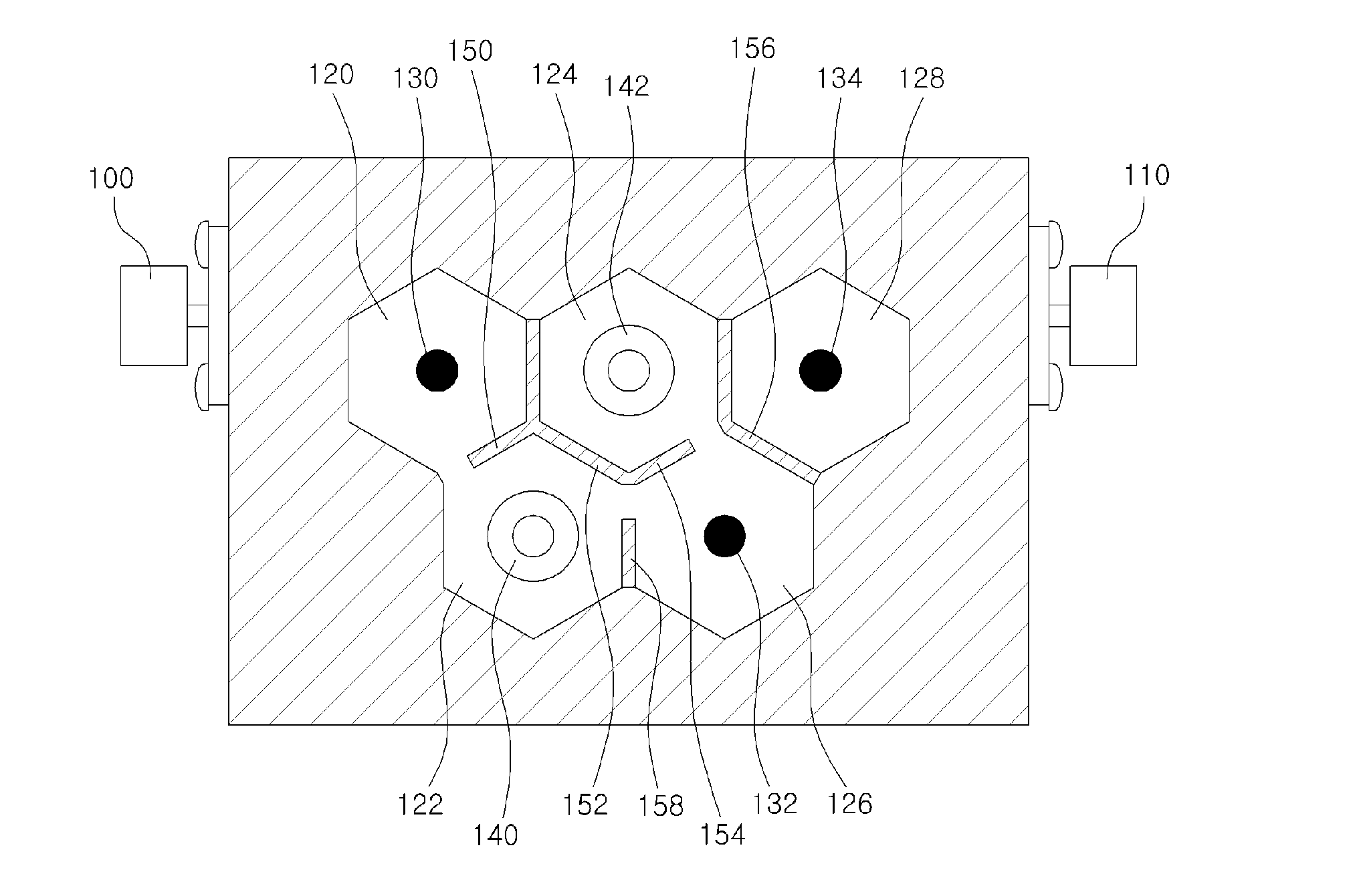
[0031]FIG. 1 is a plan view of a mixed-mode cavity filter, with the cover removed, according to a first disclosed embodiment of the invention.

[0032]Referring to FIG. 1, a mixed-mode cavity filter according to a first disclosed embodiment of the invention may include an input port 100, an output port 110, ...


PUM


Abstract

A mixed-mode cavity filter is disclosed. The disclosed cavity filter includes: at least one first cavity configured to hold a metal coaxial resonator; and at least one second cavity configured to hold a dielectric resonator, where a first coupling window is formed in a wall formed between the first cavity and the second cavity, the first coupling window includes a horizontal window formed parallel to a bottom portion and a vertical window formed perpendicularly to the bottom portion, and the horizontal window and the vertical window overlap each other in at least a partial area. A mixed-mode filter according to an embodiment of the invention can achieve a small size and a light weight while providing low losses.

Description

CROSS-REFERENCE TO RELATED APPLICATIONS[0001]This application claims the benefit of Korean Patent Application No. 10-2013-0014593, filed with the Korean Intellectual Property Office on Feb. 8, 2013, and Korean Patent Application No. 10-2014-0005195, filed with the Korean Intellectual Property Office on Jan. 15, 2014, the disclosures of which are incorporated herein by reference in their entirety.BACKGROUND[0002]1. Technical Field[0003]Embodiments of the present invention relate to a cavity filter, more particularly to a mixed-mode cavity filter in which different modes are combined.[0004]2. Description of the Related Art[0005]Advances in communication services lead to increased transmission speeds, which in turn require increases in system bandwidth, improved reception sensitivity, and minimized interference from carriers of other communication systems.[0006]As such, there is a growing demand for a broadband filter that offers low insertion loss and high rejection. Also, in order to...

Claims


Application Information

Patent Timeline
IPC IPC(8): H01P1/20
CPCH01P1/2086H01P1/2053H01P1/2084H01P1/20
Inventor CHUN, DONG-WANJANG, JAE-WONSEO, JAE-OK
Owner ACE TECH
Why Eureka
Try Eureka