Wireline Floatation Device and Method

a technology of floatation device and wireline, which is applied in the direction of cable installation on float, special purpose vessels, cables, etc., can solve the problems of catastrophic equipment loss, tool and wireline cannot be pulled out of the well, wireline either breaks, etc., and achieves the effect of increasing the depth

Active Publication Date: 2014-08-14
VON EBERSTEIN WILLIAM
View PDF10 Cites 3 Cited by
  • Summary
  • Abstract
  • Description
  • Claims
  • Application Information

AI Technical Summary

Benefits of technology

[0006]It is an object of the present invention to provide a floatation

Problems solved by technology

When this happens, the wireline either breaks or the tool and wireline cannot be pulled out of the well

Method used


Image

  • Wireline Floatation Device and Method
  • Wireline Floatation Device and Method
  • Wireline Floatation Device and Method

Examples


Embodiment Construction

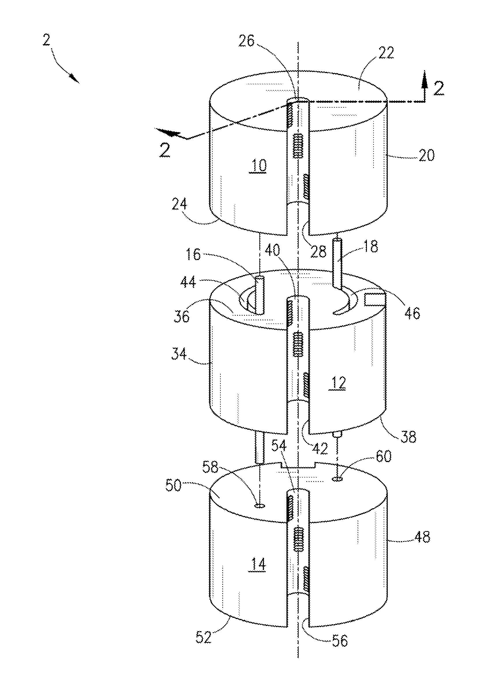
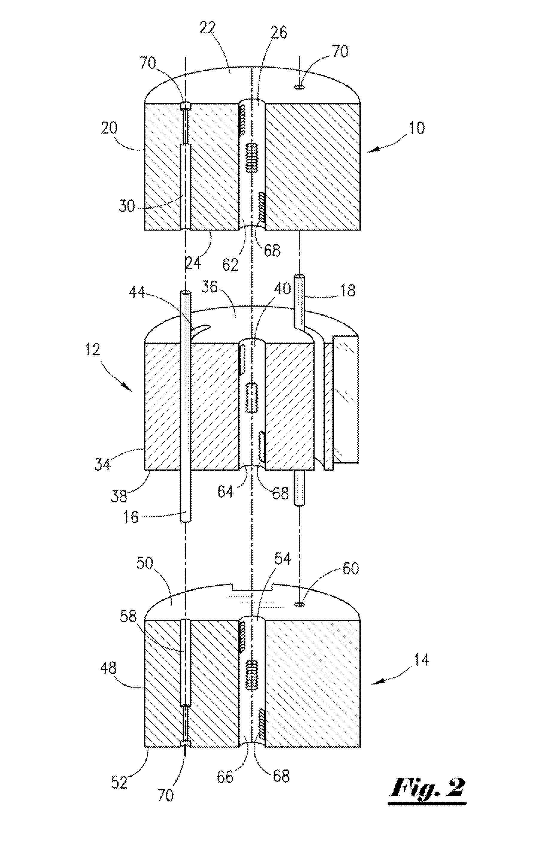
[0046]With reference to the figures where like elements have been given like numerical designation to facilitate an understanding of the present invention, and in particular with reference to the embodiment of the present invention illustrated in FIG. 1, wireline floatation device 2 is shown in a separated position and not engaged on a wireline. Device 2 may include first floatation module 10, second floatation module 12, third floatation module 14, and pin members 16 and 18. First floatation module 10, second floatation module 12, and third floatation module 14 may be cylindrically shaped. The total length of floatation modules 10, 12, 14 may but need not be in the range of five inches to one foot. Floatation modules 10, 12, 14 may each be completely or partially formed of a buoyant material. For example, the buoyant material may be a syntactic foam commercially available from CRP Corporation under the name Syntactic Foam. Other examples of buoyant material that may be used include...


PUM


Abstract

A wireline floatation device capable of reducing the weight of a wireline deployed down a well bore may include a floatation module capable of being detachably affixed to a wireline and formed at least partially of a buoyant material. A groove in the floatation module may extend longitudinally from a top face to a bottom face and laterally from an inner portion to an outer surface to receive the wireline. The groove may include a wireline receptacle portion capable of operatively housing the wireline. The floatation module may also include one or more gripping means capable of retaining the floatation module at a predetermined position on the wireline. The floatation module may further include a retaining means capable of selectively retaining the wireline within the groove. The floatation module may include a plurality of floatation modules capable of being operatively engaged to each other and detachably affixed to the wireline.

Description

FIELD OF THE INVENTION[0001]This invention relates to a floatation device and method for wireline, and more particularly to a floatation device and method for wireline that permits wireline operations to be conducted at extended depths in a well bore.BACKGROUND OF THE INVENTION[0002]Hydrocarbon reservoirs are being discovered and developed offshore in deep water tracts. Offshore drilling platforms may be anchored in water depths of more than 9,200 feet or dynamically positioned in water depths greater than 10,000 feet. Offshore wells are being drilled to depths that exceed 34,000 feet.[0003]Wireline operations are often conducted on offshore platforms. Wireline units, also known as logging units, may be used to survey hydrocarbon wells to determine their geological, petrophysical, or geophysical properties. An electronic measuring instrument or logging tool is lowered into the well bore on a steel cable known as a wireline. The logging tool takes measurements and transmits them to t...

Claims


Application Information

Patent Timeline
IPC IPC(8): F16L1/24
CPCF16L1/24H02G1/10H02G3/0475H02G9/12
Inventor SNYDER, II, GARY ALLEN
Owner VON EBERSTEIN WILLIAM
Why Eureka
Try Eureka