Elevator arrangement and method

Inactive Publication Date: 2014-08-21
KONE CORP
View PDF13 Cites 19 Cited by
  • Summary
  • Abstract
  • Description
  • Claims
  • Application Information

AI Technical Summary

Benefits of technology

[0004]A problem in prior-art solutions has been that the hoisting arrangements needed for lifting the supporting platform are very space-consuming, are complex and are not sufficiently quick to use. More particularly the support points needed for shifting and positioning the machine room platform are difficult to arrange. It would not be desirable to separately arrange numerous support points in a building. It has been noticed that the difficulty of finding support points that are sufficiently stable and durable effectively limits the maximum height to which a jump-lift can, with a reasonable work input, reach. A worksite crane must sometimes be used for shifting the machine room platform, because the aforementioned problems make other solutions so awkward. Another problem has been, generally speaking, the demanding installation environment, which has set numerous practical challenges, which are connected to the smooth-running and safety of the installation and to the durability of structures. These are, inter alia, the space usage and complexity of the hoisting arrangement of the machine room platform, the center of mass and stability of the machine room platform during the lifting and while in position, the center of mass and stability of the support arrangement to be used for the lifting during the lifting and while in position, the placement producing a suitable balance of the support locking mechanism, the cramped layout of the machine room platform, suitable hoisting devices, the dimensioning of the hoisting machine for the final travel height, routing of the ropes with adequate run clearances, correct configuration of the rope length, the need for safe and spacious working space and position. These numerous variables that must be taken into account affect each other directly or indirectly and their overall effect is that the structure easily becomes complex and heavily built, and requires a lot of space. Taking these challenges into account, there has been a need to further simplify the support structure to be lifted in a jump lift and to reduce the weight to be lifted in a jump lift. Likewise, there has been a need to further develop the safety and speed of the method.
[0005]The aim of the present invention is to solve the aforementioned problems of prior-art solutions as well as the problems disclosed in the description of the invention below. The aim is thus to produce an improved method in the fabrication of an elevator and an improved construction-time elevator arrangement. With the solution according to the invention, it is possible to directly or indirectly affect numerous problems of jump-lifts.
[0006]The elevator arrangement according to the invention comprises an elevator hoistway, an elevator c

Problems solved by technology

A problem in prior-art solutions has been that the hoisting arrangements needed for lifting the supporting platform are very space-consuming, are complex and are not sufficiently quick to use.
More particularly the support points needed for shifting and positioning the machine room platform are difficult to arrange.
It has been noticed that the difficulty of finding support points that are sufficiently stable and durable effectively limits the maximum height to which a jump-lift can, with a reasonable work input, reach.
A worksite crane must sometimes be used

Method used


Image

  • Elevator arrangement and method
  • Elevator arrangement and method

Examples


Embodiment Construction

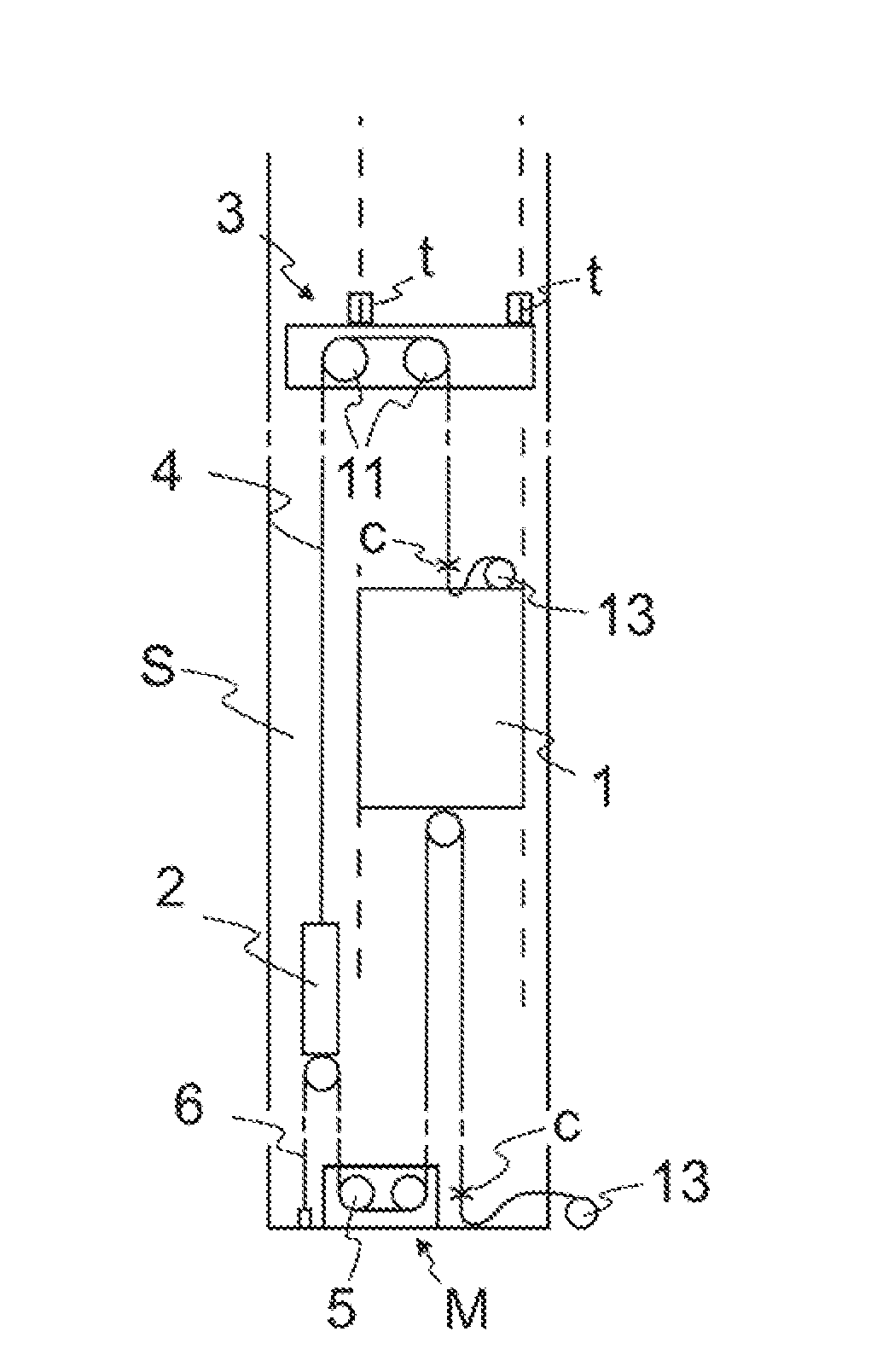
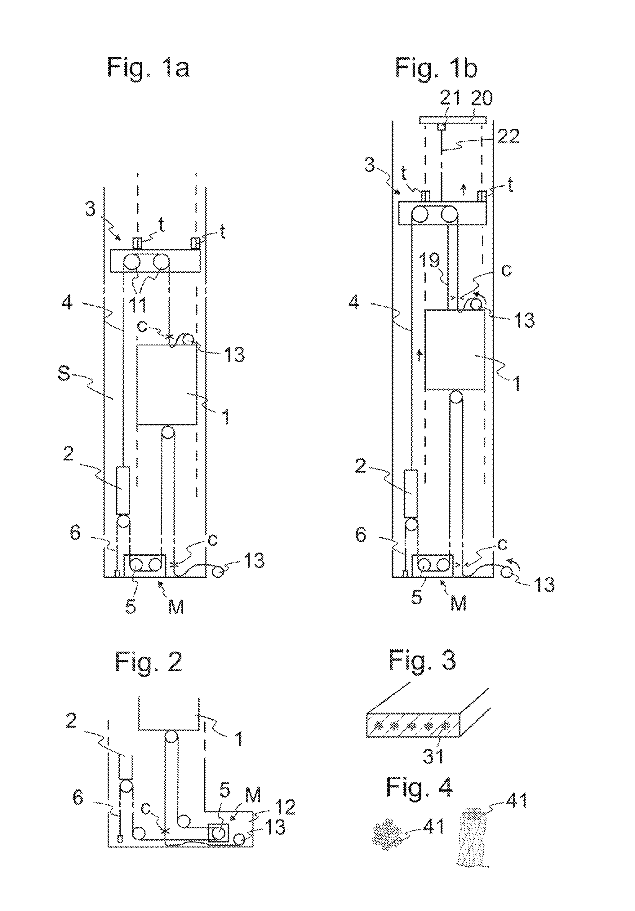
[0040]FIG. 1a presents an elevator arrangement according to the invention, which arrangement is achieved by performing the phases of the method according to the invention in the fabrication of the elevator. In conclusion of the arrangement of FIG. 1a preferably the procedures of the method according to the invention have been performed. The figure presents an arrangement in a phase of the method, in which phase a partially completed elevator is used during the construction-time of the elevator, before the elevator hoistway S is completed throughout its full length. The elevator car 1 serves passengers in the already completed bottom part of the elevator hoistway S at the same time as the top part of the elevator hoistway S above the supporting platform 3 is being constructed. These work phases preferably include at least installation of the guide rails G. The elevator arrangement comprises a supporting platform 3, displaceable in the vertical direction in the elevator hoistway S, fo...


PUM


Abstract

An elevator arrangement, includes an elevator hoistway, an elevator car, which is arranged to travel in the elevator hoistway, a counterweight, a movable supporting platform above the elevator car, suspension roping, which is connected to the elevator car and to the counterweight, and supports them while suspended from the supporting platform, and a hoisting machine, which includes a device configured to move the roping. The elevator arrangement also includes a hoisting machine and traction roping that are separate from the supporting platform, which hoisting machine is in power transmission connection via the traction roping with the elevator car and with the counterweight.

Description

FIELD OF THE INVENTION[0001]The object of the invention is an elevator arrangement and a method in the fabrication of an elevator, which elevator is preferably an elevator applicable to passenger transport and / or freight transport, and in which method and elevator arrangement the elevator is taken / can be taken into service use already during the time of its construction.BACKGROUND OF THE INVENTION[0002]In connection with so-called jump-lifts, the elevator hoistway is taken into use already before the full length of the elevator hoistway has been completed. The top part of the elevator hoistway is constructed at the same time as an elevator car moving in the already completed bottom part of the elevator hoistway serves people on the lower floors of the building. In jump-lifts, the elevator car moving in the lower part of the elevator hoistway is supported and moved during the construction-time use suspended on hoisting ropes that are supported by a supporting platform in the elevator...

Claims


Application Information

Patent Timeline
IPC IPC(8): B66B11/00
CPCB66B11/0045B66B19/00B66B7/062B66B11/009B66B9/187B66B11/004
Inventor ALASENTIE, PENTTI
Owner KONE CORP
Why Eureka
Try Eureka