Eureka AIR delivers breakthrough ideas for toughest innovation challenges, trusted by R&D personnel around the world.

Method for optimizing the yield of a partially shaded photovoltaic array

Active Publication Date: 2014-08-21
KACO NEW ENERGY GMBH
View PDF7 Cites 3 Cited by
  • Summary
  • Abstract
  • Description
  • Claims
  • Application Information

AI Technical Summary

Benefits of technology

The invention is about a way to increase the amount of sunlight that a photovoltaic array can collect, while minimizing the loss of yield caused by shading of the solar modules.

Problems solved by technology

This results in a correspondingly low photovoltaic current and a strong voltage drop across the shaded photovoltaic modules.
Without searching processes, it is possible that only one local maximum is found, which may have the consequence of considerable losses in yield.
If, however, a searching process is started without there being any shading, losses in yield occur.

Method used


Image

  • Method for optimizing the yield of a partially shaded photovoltaic array
  • Method for optimizing the yield of a partially shaded photovoltaic array
  • Method for optimizing the yield of a partially shaded photovoltaic array

Examples


Embodiment Construction

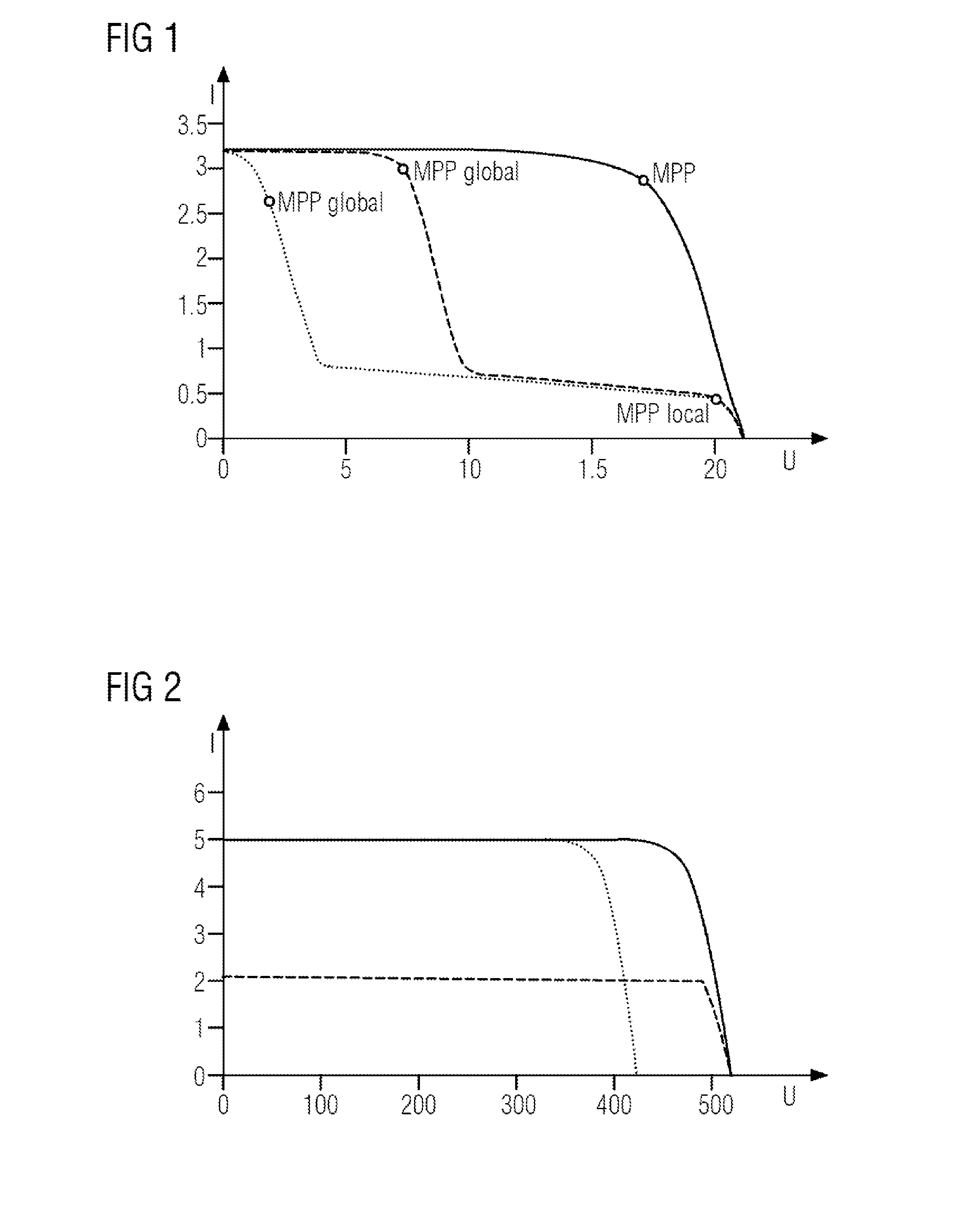
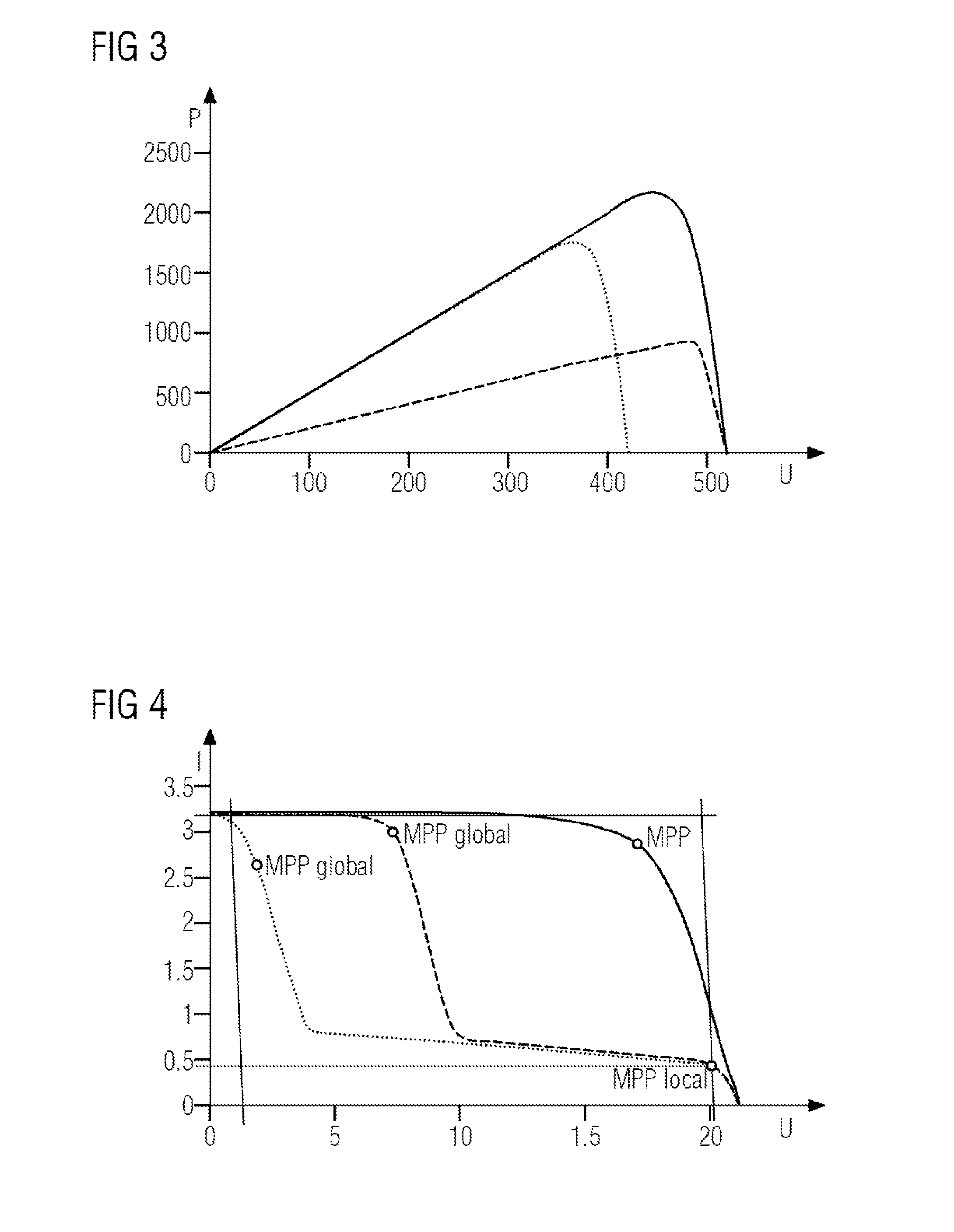
[0022]With ideal photovoltaic arrays (PV arrays) without partial shading of the photovoltaic modules, as represented by the solid line in FIG. 1, the maximum energy yield (Maximum Power Point MPP) is relatively easy to determine by commonly used searching processes. In the case of partial shading, however, a number of maxima are obtained as shown in FIG. 1. Thus, the operating point found at the given time may only represent a local power maximum MPPlocal. The global power maximum MPPglobal, however, lies at a different point and is also dependent on whether a connection of the photovoltaic modules to a bypass diode exists—as represented by the dashed line—or not (see dotted line). In order to find the global power maximum MPPglobal, the local power maximum MPPlocal must be abandoned, for example by running through the entire IU characteristic (current-voltage characteristic) in scanning steps to be correspondingly defined, it not being certain a priori whether there is a global pow...


PUM


Abstract

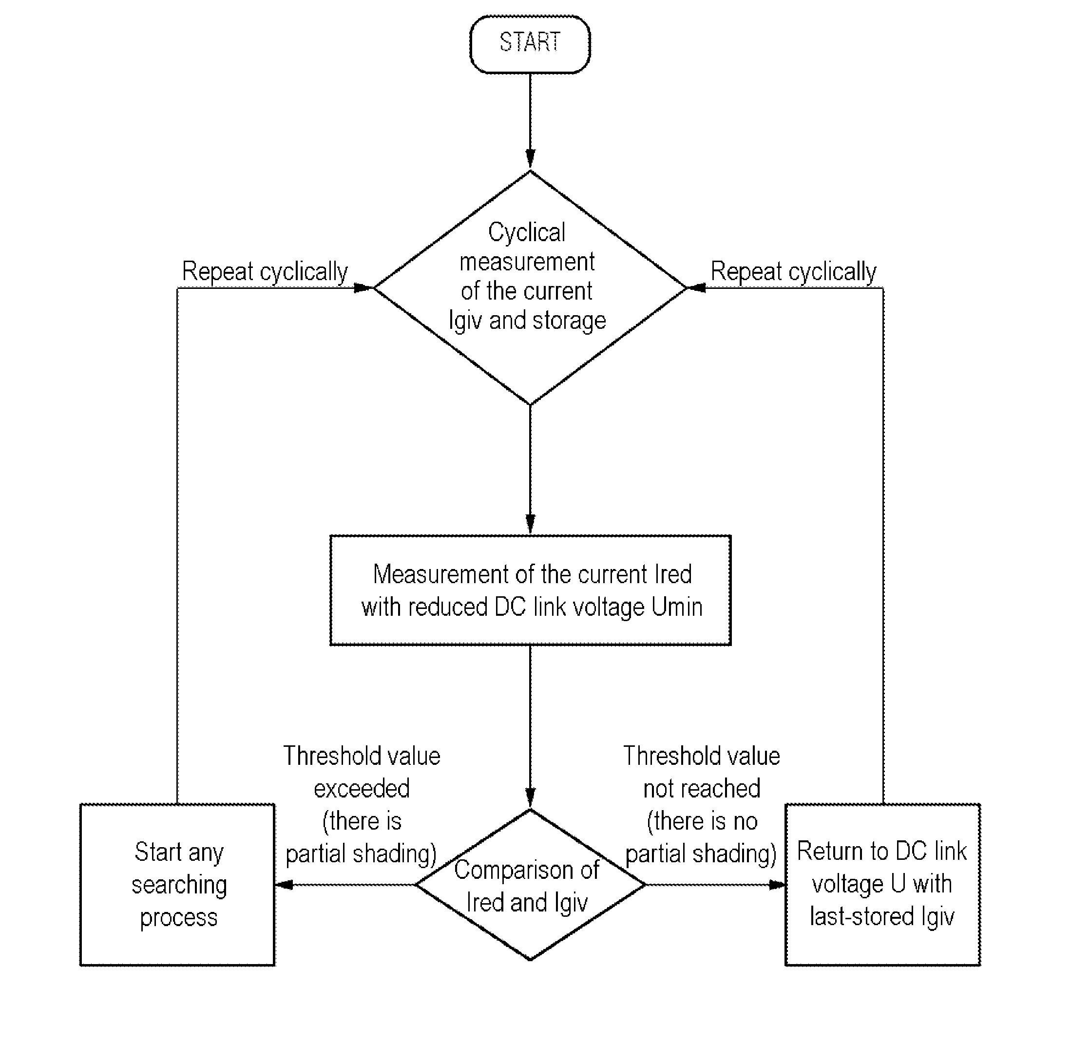
A method for optimizing the yield of a photovoltaic array with an inverter is provided. The method includes: a) cyclically measuring a current (Igiv) and a DC link voltage (U) when controlling the inverter by a MPP method (Maximum Power Point) and storing a measured current value, b) lowering the DC link voltage (U) to a value that exceeds by no more than 100% a minimum DC link voltage (Umin) admissible for operation of the inverter, c) measuring a current (Ired) with a reduced DC link voltage and comparing it with a previously stored value at a given time for the current (Igiv), d) if a prescribed threshold for a difference between the two currents (Ired, Igiv) is exceeded, a searching process for a global MPP (Maximum Power Point) is initiated, e) otherwise, operation is continued at a power maximum (MPP) with a last-stored current value for the current (Igiv).

Description

CROSS REFERENCE TO RELATED APPLICATIONS[0001]This application claims the benefit of German Application No. DE 102013202600.5 filed Feb 19, 2013, incorporated by reference herein in its entirety.FIELD OF INVENTION[0002]The present invention relates to a method for optimizing the yield of a partially shaded photovoltaic array.BACKGROUND OF INVENTION[0003]Photovoltaic arrays (PV arrays) are usually operated on the basis of a control method in which the maximum energy yield is obtained at the maximum power MPP (Maximum Power Point), for which reason the term MPP method is also used for this. In the case of partial shading of a photovoltaic array due to shading of one or more photovoltaic modules, the current-voltage characteristic (IU characteristic) of the photovoltaic array concerned changes, since the shaded photovoltaic modules represent a high ohmic resistance. Referred to here as the voltage is the DC link voltage U that can be controlled by means of an inverter. This results in a...

Claims


Application Information

Patent Timeline
IPC IPC(8): H02J1/00
CPCH02J1/00G05F1/67H02J2300/26H02J3/381Y02E10/56
Inventor BLEISTEINER, THOMASHAUG, MARCREIHER, KARSTEN
Owner KACO NEW ENERGY GMBH
Why Eureka
Eureka Blog
Learn More