Drive unit and method for operating the drive unit

a technology of drive unit and drive unit, which is applied in the direction of motor/generator/converter stopper, mechanical energy handling, dynamo-electric converter control, etc., can solve the problems of large overall size, additional mounting elements involve additional costs and effort, etc., and achieve the effect of reducing the size of the arrangement and robust and durable drive unit construction

Inactive Publication Date: 2014-08-21
BROSE FAHRZEUGTEILE GMBH & CO KG HALLSTADT (DE)
View PDF6 Cites 8 Cited by
  • Summary
  • Abstract
  • Description
  • Claims
  • Application Information

AI Technical Summary

Benefits of technology

[0004]Accordingly, there is the need to provide an enhanced drive unit with a break, ensuring a robust and durable drive unit construction and requiring a reduced size of the arrangement.

Problems solved by technology

These additional mounting elements involve additional costs and effort when manufacturing the motor housing and the breaking unit.
Further to this, such a device comprising a motor and additional breaking means leads to an overall large-sized.

Method used


Image

  • Drive unit and method for operating the drive unit
  • Drive unit and method for operating the drive unit
  • Drive unit and method for operating the drive unit

Examples


Embodiment Construction

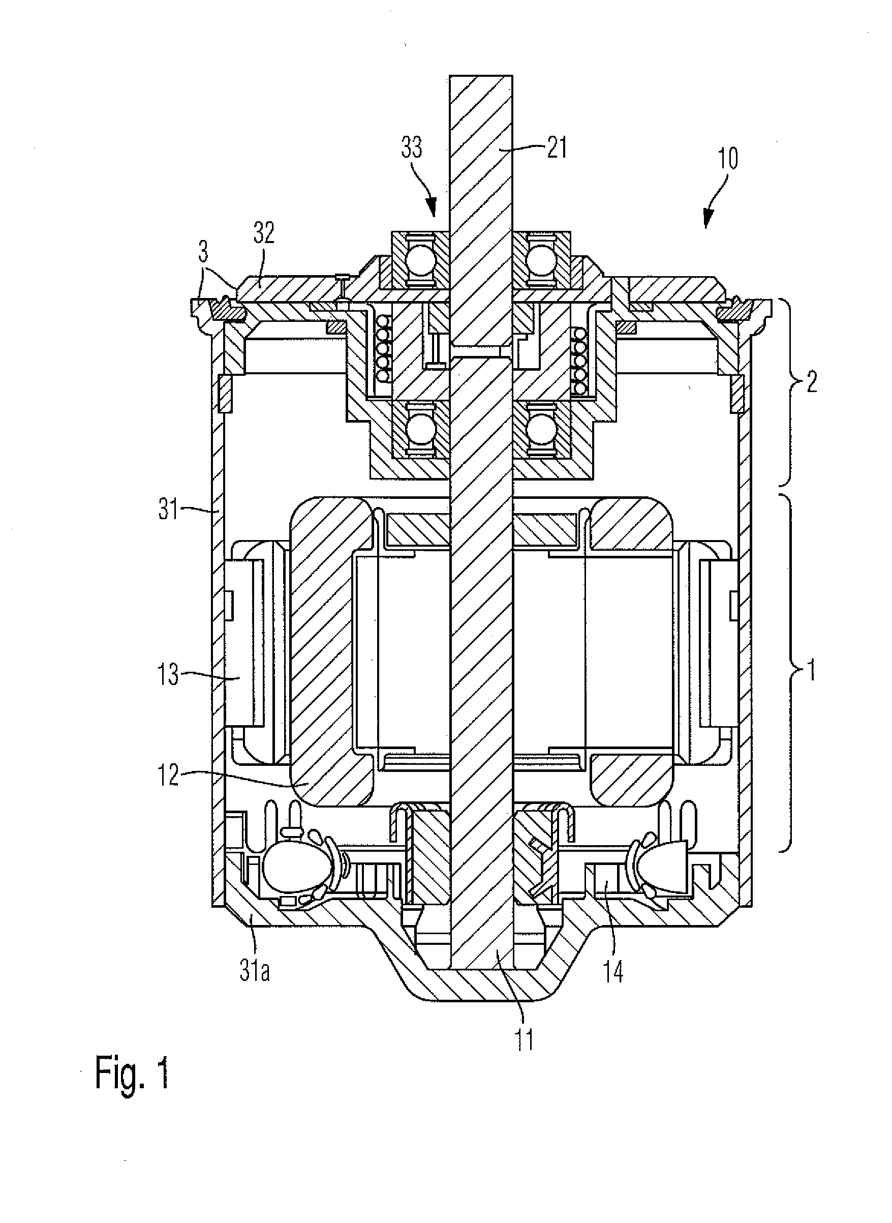
[0031]With reference firstly to FIG. 1 of the drawings, a drive unit 10 for driving a powered vehicle window or for adjusting a seat part is shown. The drive unit 10 comprises an electric drive assembly 1 and a break assembly 2. The electric drive assembly 1 further comprises a rotor 12 as well as a stator assembly. The stator assembly in this configuration comprises metallic housing 31 and at least one permanent magnet 7. The metallic housing 31 is made of magnetic flux conductive material. The at least one magnet 7 is fastened to housing 31 by means of adhesive of clips 13. The rotor 12 is mounted on shaft 11 to rotate about an axis. The electric drive assembly 1 is further connected to the power by means of a brush card 14, which is arranged at the bottom of the electrical drive assembly 1.

[0032]Alternatively, other types of motors for an electric drive assembly 1 are also possible. For example the electric drive assembly 1 may be an electrically of electromagnetically induced mo...


PUM


Abstract

A drive unit for operating a device, in particular a device in a vehicle and a method for operating a drive unit are provided. An electrical drive assembly and a break assembly are combined and arranged together in a common housing. The breaking assembly could be a mechanical breaking assembly or an electrical break assembly. The break assembly automatically locks the shaft of the electrical drive assembly and thus provides self-locking capabilities.

Description

FIELD OF THE INVENTION[0001]The present invention is directed to a drive unit for actuating devices in a vehicle and a method for operating the drive unit.BACKGROUND OF THE INVENTION[0002]Modern automobiles comprise a plurality of auxiliary drive units. In particular electrically operated drive units, such as electric motors, are used for transfer case applications, engine cooling fan modules, operating windows, seat parts or other accessories in an automobile. In some applications, the operated device has to remain in the position which has been set up by the drive unit. For example, in transfer case application the electric motor with a holding break provides a torque to shift the transfer case to all required positions over its operating range, and further provides a holding torque required at any specific position. Furthermore, a window or a seat part is locked after the drive unit stops operating. Thus, the position of the window or the seat part cannot be changed by an externa...

Claims


Application Information

Patent Timeline
Patent Type & Authority Applications(United States)
IPC IPC(8): H02K7/102H02P3/04H02K7/112H02K7/108
CPCH02K7/1021H02K7/1125H02P3/04H02K7/108H02K7/10
Inventor SIMOFI-ILYES, ATTILASTAMENIC, MILENKOGROPPEL, MICHAELILLINGWORTH, RICHARD
Owner BROSE FAHRZEUGTEILE GMBH & CO KG HALLSTADT (DE)
Why Eureka
Try Eureka