Three-dimensional surface inspection system using two-dimensional images and method

a three-dimensional surface and image technology, applied in the field of three-dimensional surface inspection systems, can solve the problems of time-consuming and costly, known systems and methods are time-consuming and costly, and known three-dimensional capture systems are very time-consuming to use and costly. to achieve the effect of simplifying the procedure of three-dimensional captur

Inactive Publication Date: 2014-08-21
SIEMENS AG
View PDF6 Cites 12 Cited by
  • Summary
  • Abstract
  • Description
  • Claims
  • Application Information

AI Technical Summary

Benefits of technology

[0006]It is therefore the object of the present invention to solve the foregoing pr

Problems solved by technology

But, three-dimensional capture by two-dimensional photography is not rapidly and easily accomplished by known three-dimensional capture processes and apparatus.
Furthermore, when an objective of the three-dimensional capture is to enable a

Method used


Image

  • Three-dimensional surface inspection system using two-dimensional images and method
  • Three-dimensional surface inspection system using two-dimensional images and method
  • Three-dimensional surface inspection system using two-dimensional images and method

Examples


Embodiment Construction

[0017]The description and the figures illustrate merely exemplary embodiments of the invention.

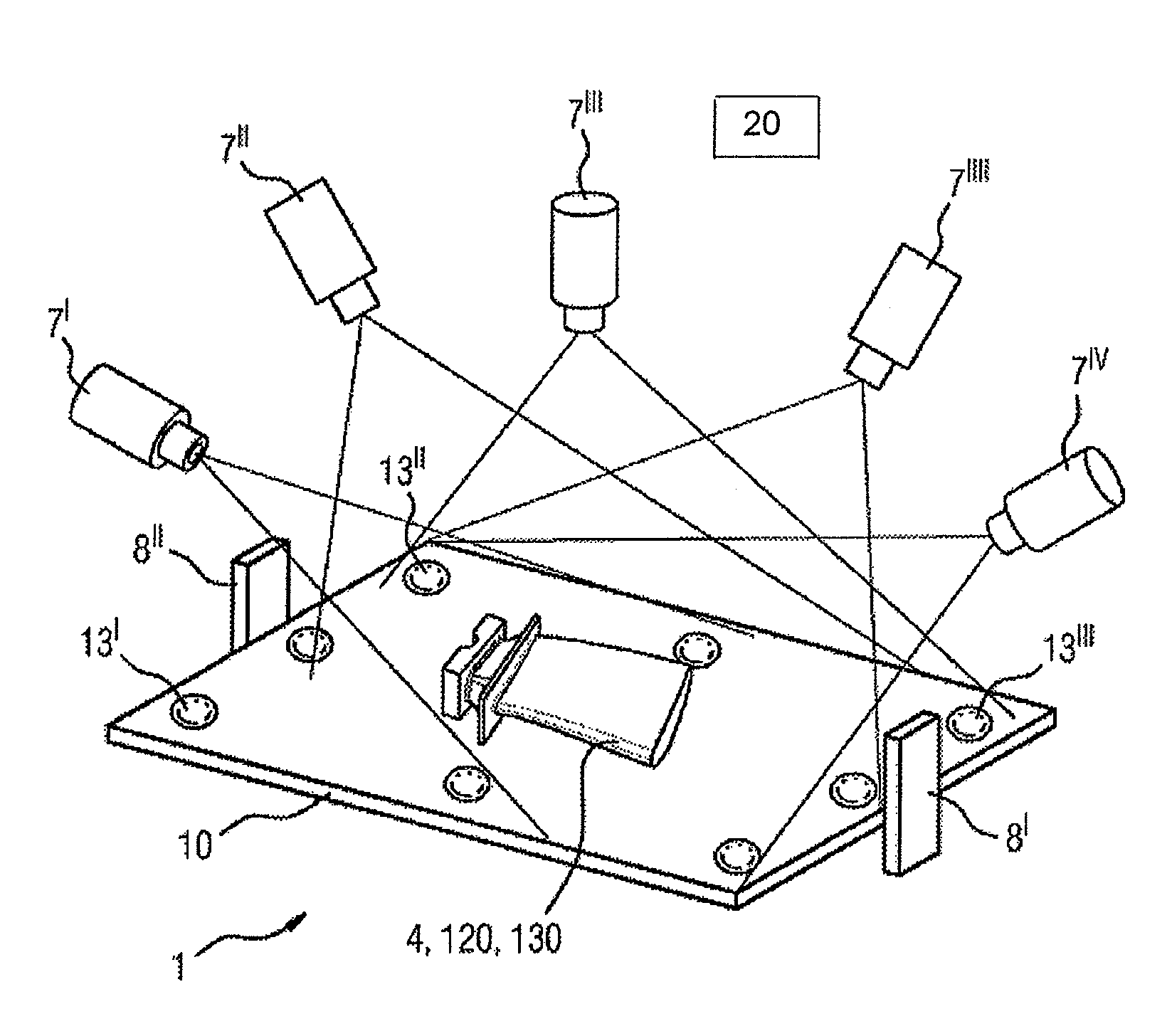
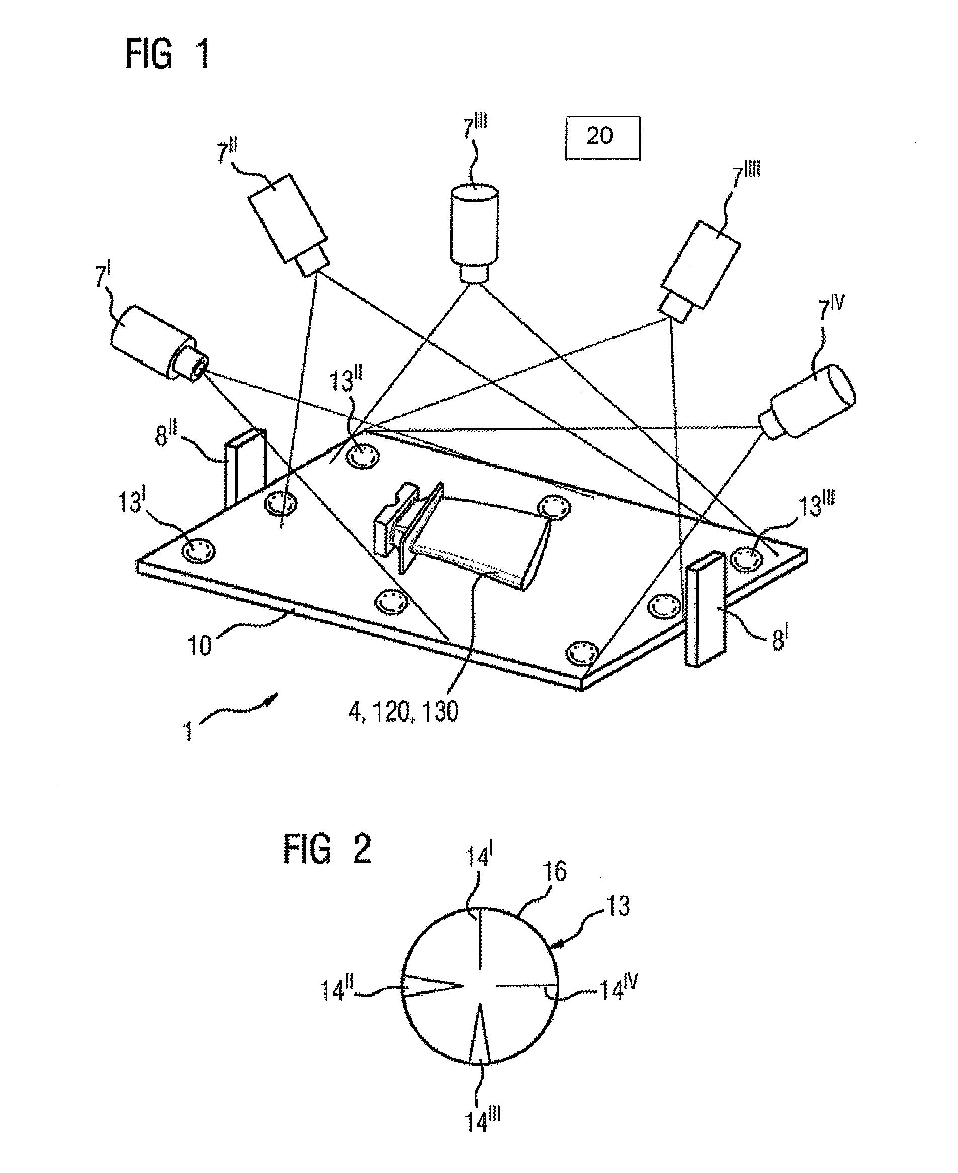
[0018]FIG. 1 illustrates a three-dimensional surface inspection system 1 according to the invention. The three-dimensional surface inspection system 1 has a measurement stage 10, on which the component 4, 120, 130 to be inspected is located.

[0019]Around the component 4, 120, 130, at least one camera 7′ is present, the position of which is changed. Alternatively, a plurality of cameras 7′, . . . , 7V, . . . , which are preferably fixedly mounted, are used.

[0020]The cameras 7′, 7″ are arranged such that they capture the entire surface of the component 4, 120, 130 which faces away from the measurement stage 10.

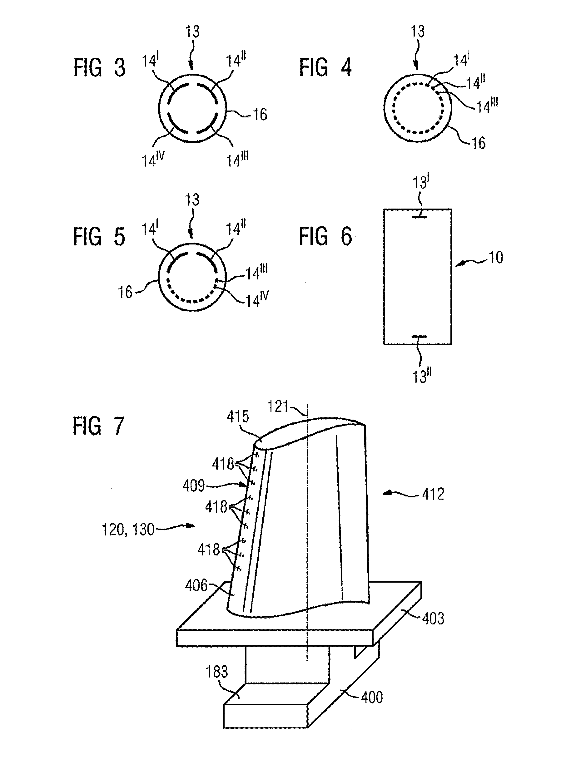
[0021]The mounting of the cameras 7′, 7″, . . . can be varied, depending on the types of components. For turbine blades 120, 130 of varying size and type (moving blade 120 or guide vane 130), the same fixed mounting of cameras 7′, 7″, . . . can be used.

[0022]At least one reference mark ...


PUM


Abstract

The three-dimensional real structure of a component can be captured by means of best fit by simply recording two-dimensional images and comparing a known three-dimensional model. A component is placed on a measurement stage having reference marks and is photographed several times in two-dimensions. The photo recordings are compared with a three-dimensional model of the component. A three-dimensional model is produced using best fit of the two-dimensional recordings and the stored model.

Description

CROSS-REFERENCE TO RELATED APPLICATIONS[0001]The present application is a 35 U.S.C. §111 Continuation in Part of International Application PCT / EP2012 / 068046, filed Sep. 14, 2012, which claims priority of European Patent Application No. 11187504.3, filed Nov. 2, 2011, the contents of which are incorporated by reference herein. The PCT International Application was published in the German language.FIELD OF THE INVENTION[0002]The invention relates to a three-dimensional surface inspection system using two-dimensional recordings.TECHNICAL BACKGROUND[0003]For many components, 100% optical examination of the entire three-dimensional component surfaces is necessary. This comprises, for example in turbine blades, the orientation of the cooling-air holes and the entire coating.[0004]Optical examination and three-dimensional capture of a component involves known processes and apparatus. But, three-dimensional capture by two-dimensional photography is not rapidly and easily accomplished by kno...

Claims


Application Information

Patent Timeline
IPC IPC(8): G01N21/95G01B11/245
CPCG01B11/245G01N21/95G01B11/25
Inventor JAHNKE, RONNYSCZEPUREK, TRISTAN
Owner SIEMENS AG
Why Eureka
Try Eureka