
Wind turbine blade having twisted spar web

a technology of wind turbine blades and spar webs, applied in wind turbines, reaction engines, motors, etc., to achieve the effects of reducing torsional rigidity, increasing torsional flexibility, and decoupling tower stiffness

Inactive Publication Date: 2014-08-21
SIEMENS AG
View PDF2 Cites 2 Cited by
  • Summary
  • Abstract
  • Description
  • Claims
  • Application Information

AI Technical Summary

Benefits of technology

This patent aims to design a new type of wind blade that is stronger and lighter. Prior to this invention, wind blade designs often had strength requirements that were higher than necessary, which resulted in a heavy spar. The new design allows for the strength of the spar to be specifically tailored to resist local deflection forces, making the blade lighter and more flexible. This flexibility helps the blade to become aeroelastic, reducing the angle of attack of the blade with respect to the relative wind, and decreasing transient stresses on the blade. Overall, the new design improves the strength and flexibility of wind blades, making them more efficient and durable.

Problems solved by technology

Furthermore, because blade stiffness has become a primary design concern, and because prior art spar webs could not tailor the spar web strength to resist tower deflection, prior art spar webs were built to standards much higher than blade strength alone (as opposed to stiffness) required.

Method used


Image

  • Wind turbine blade having twisted spar web
  • Wind turbine blade having twisted spar web
  • Wind turbine blade having twisted spar web

Examples


Embodiment Construction

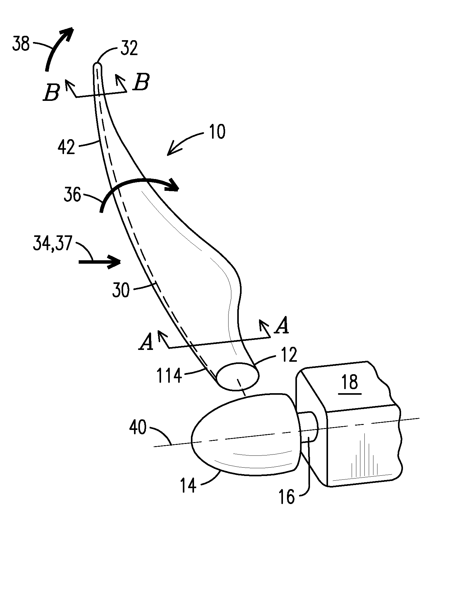
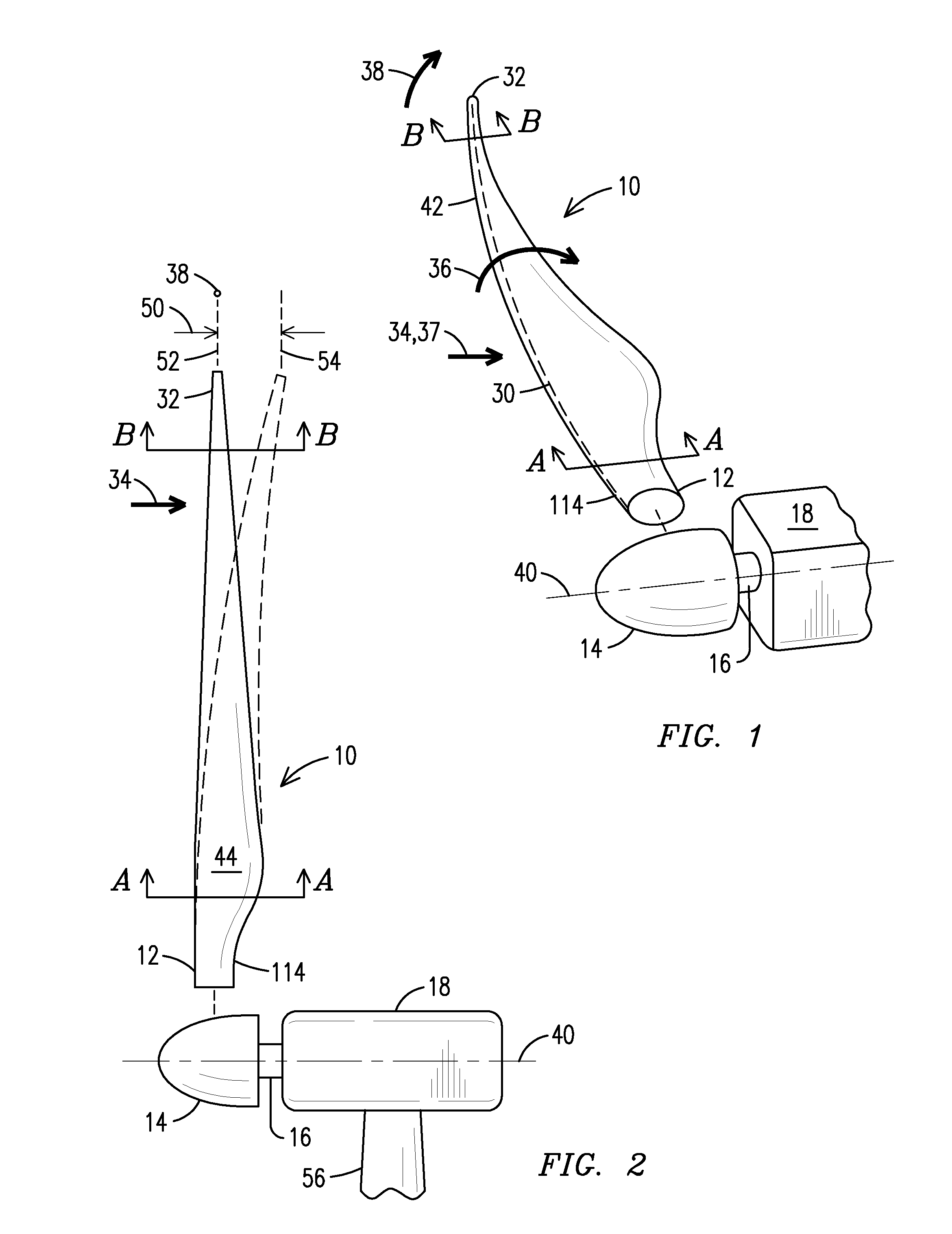
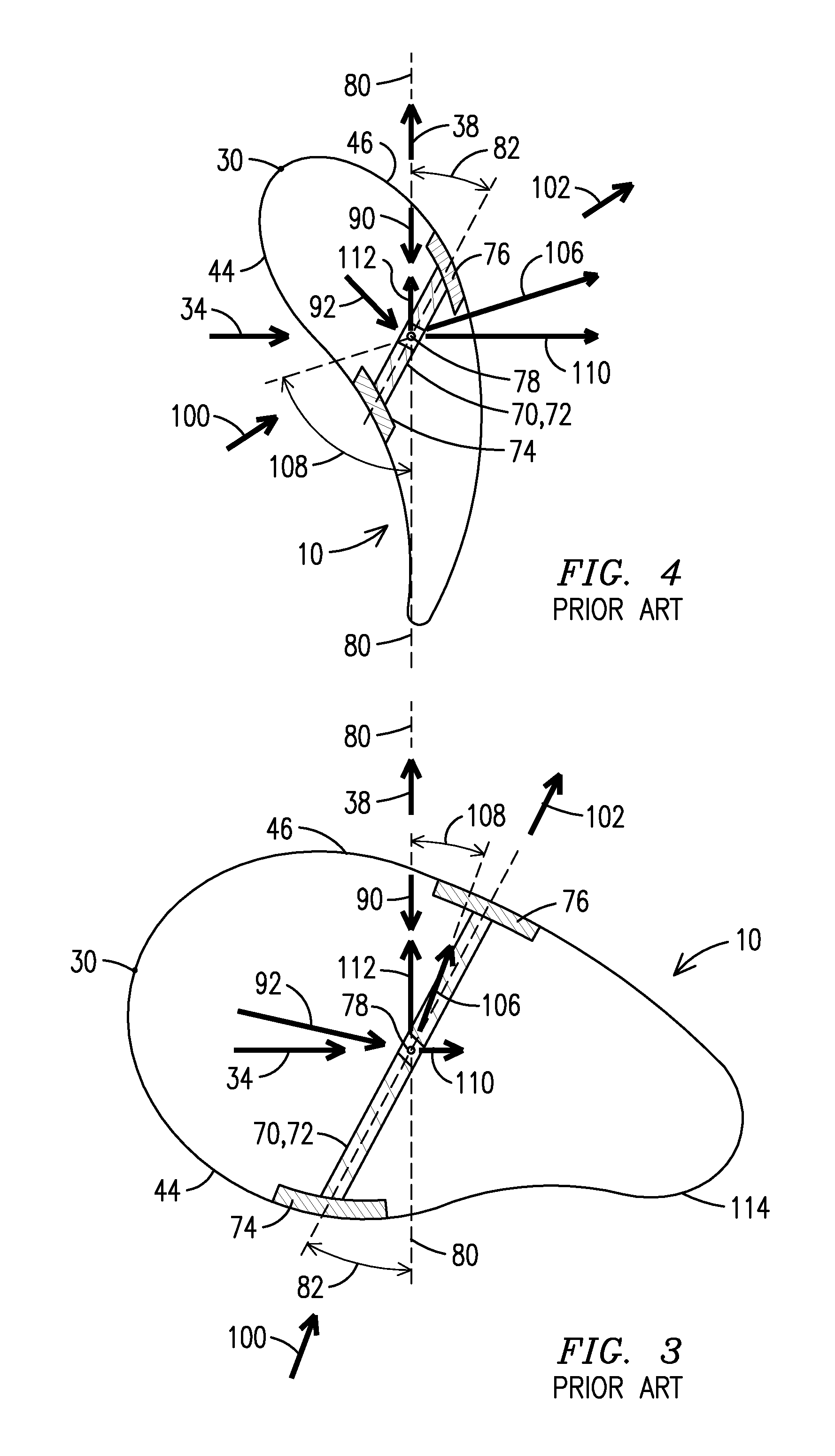
[0020]The present inventor has recognized that blade design has evolved from designing blades of sufficient strength to designing blades of stiffness sufficient to prevent the blade from colliding with the tower support. The present inventor has also recognized that local forces change from a base of the blade to a tip of the blade. In particular, at the base of the blade rotational forces (within a plane of rotation) have “accumulated” from the tip to the blade to the base, while tower deflection forces (toward the tower) are negligible. A skin of the blade is very robust at the blade and can withstand the deflection forces itself, but may need the assistance of a structural spar to handle the rotational forces. In contrast, at the tip of the blade the rotational forces are negligible, while deflection forces have “accumulated” from the base to the tip, resulting in greater tower deflection. Since the blade is thin and oriented close to parallel to the plane of rotation, it can han...


PUM


Abstract

A radially twisted wind turbine blade (10), including a radially twisted spar web (122), wherein a center (78) of a radial cross section of a base (12) of the blade rotates within a plane of rotation (80), and wherein at a base (12), a radial cross section of the spar web forms a first angle (82) with the plane of rotation, and at a tip (32) a radial cross section of the spar web forms a second angle (130) with the plane of rotation different than the first angle.

Description

FIELD OF THE INVENTION[0001]The present invention relates to wind turbine blades. In particular, the present invention relates to a wind turbine blade that allows for an increased resistance to flap deflection without adding weight or increasing torsional rigidity.BACKGROUND OF THE INVENTION[0002]Wind turbines include wind turbine blades that are secured to a rotor hub. The blades and rotor rotate about an axis of rotation and drive a rotor shaft. The rotor shaft, in turn, drives a generator arrangement disposed in a nacelle located adjacent to the rotor hub. The generator arrangement and nacelle are disposed atop a support tower.[0003]At a base of the blade a linear velocity for any given radial location is determined by the formula Vlinear=rω, where r is a radius and w is a rotational velocity. Thus, at the base, where the radius is shorter, the Vlinear is less than at the tip of the blade. Assuming the blade is rotation in when there is no wind, the linear velocity of the blade c...

Claims


Application Information

Patent Timeline
Patent Type & Authority Applications(United States)
IPC IPC(8): F01D5/14
CPCF01D5/141F03D1/0675F05B2240/311F05B2250/71Y02E10/72
Inventor SCHIBSBYE, KARSTEN
Owner SIEMENS AG
Learn More