
Wind turbine blade having twisted spar web

A technology of wind turbines and spars, which is applied in the direction of the wind engine, wind engine, and blade support elements in the same direction as the wind, and can solve the problem of adding weight to the blades

Inactive Publication Date: 2015-11-18
SIEMENS AG
View PDF7 Cites 2 Cited by
  • Summary
  • Abstract
  • Description
  • Claims
  • Application Information

AI Technical Summary

Problems solved by technology

The spars add strength and rigidity, but also add weight to the blades

Method used


Image

  • Wind turbine blade having twisted spar web
  • Wind turbine blade having twisted spar web
  • Wind turbine blade having twisted spar web

Examples


Embodiment Construction

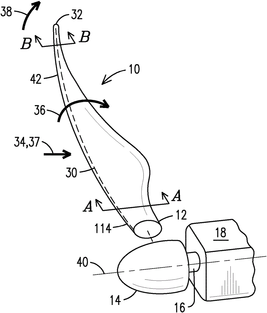
[0020] The inventors of the present invention have realized that blade design has evolved from designing blades with sufficient strength to designing blades with sufficient stiffness to prevent the blade from colliding with the tower support. The inventors of the present invention have also realized that the local force changes from the base of the blade to the tip of the blade. Specifically, at the base of the blade, rotational forces (in the plane of rotation) "build up" from tip to blade to base, while tower deflection forces (toward the tower) are negligible. The skin of the blade is very strong at the blade and is able to withstand its own deflection forces, but may require the assistance of a structural spar to handle rotational forces. Conversely, at the tip of the blade, the rotational force is negligible, while the deflection force has "built up" from the base to the tip, resulting in greater tower deflection. Because the blade is thin and oriented nearly parallel to...


PUM


Abstract

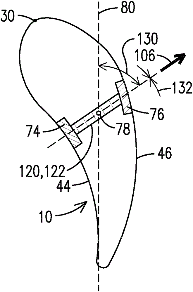
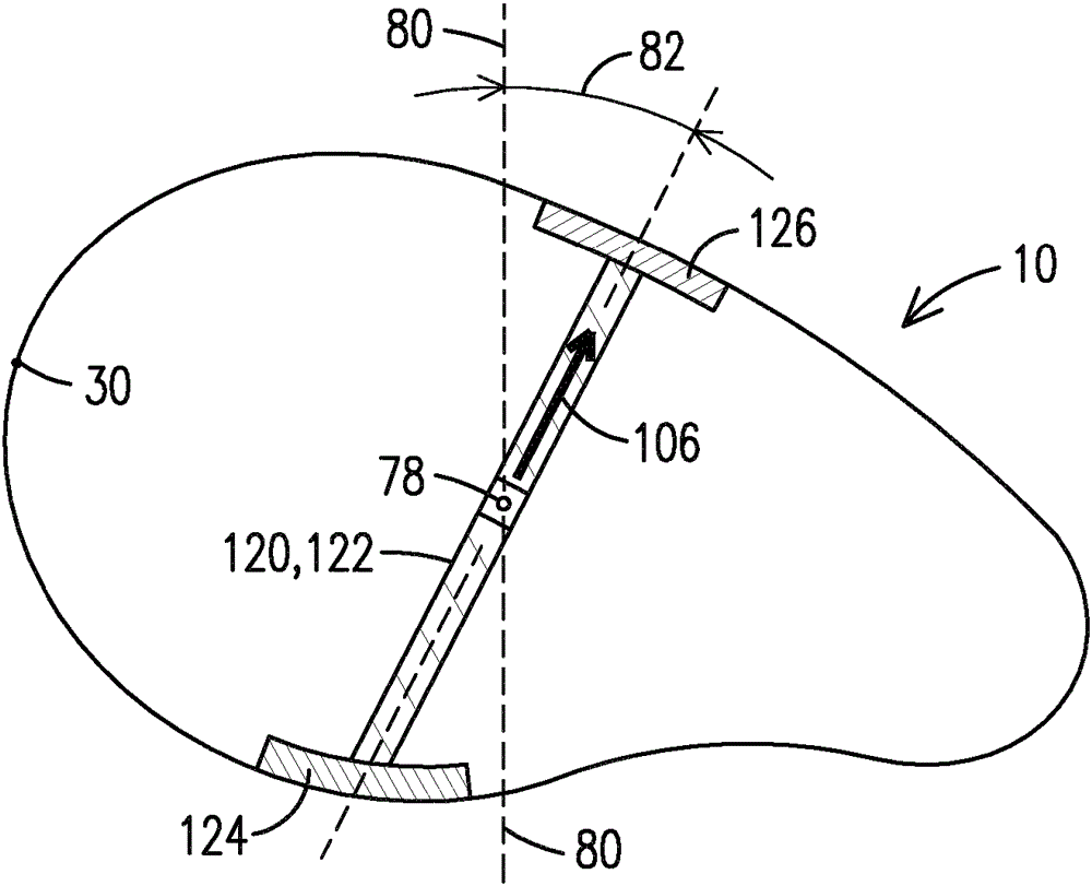
A radially twisted wind turbine blade (10), including a radially twisted spar web (122), wherein a center (78) of a radial cross section of a base (12) of the blade rotates within a plane of rotation (80), and wherein at a base (12), a radial cross section of the spar web forms a first angle (82) with the plane of rotation, and at a tip (32) a radial cross section of the spar web forms a second angle (130) with the plane of rotation different than the first angle.

Description

technical field [0001] The present invention relates to wind turbine blades. In particular, the present invention relates to a wind turbine blade that allows increased resistance to flap deflection without adding weight or increasing torsional stiffness. Background technique [0002] A wind turbine includes wind turbine blades secured to a rotor hub. The blades and rotor rotate about an axis of rotation and drive the rotor shaft. Said rotor shaft in turn drives a generator arrangement arranged in a nacelle located adjacent to the rotor hub. The generator arrangement and nacelle are arranged on top of the support tower. [0003] At the base of the blade, for any given radial position, the linear velocity is given by the formula V linear =rω, where r is the radius and ω is the rotational speed. Therefore, at the base of the shorter radius, V linear smaller than at the tip of the blade. Assuming the blades are rotating when there is no wind, the linear velocity of the bl...

Claims


Application Information

Patent Timeline
Patent Type & Authority Applications(China)
IPC IPC(8): F03D1/06
CPCF01D5/141F03D1/0675F05B2240/311F05B2250/71Y02E10/721Y02E10/72
Inventor K.希布斯拜
Owner SIEMENS AG
Learn More