Molding artificial teeth in denture base disc

a technology of denture base and artificial teeth, which is applied in the direction of artificial teeth, dental prosthetics, impression caps, etc., can solve the problems of denture teeth dislodging from the denture base, and tooth dislocation

Active Publication Date: 2014-08-21
GLOBAL DENTAL SCI
View PDF1 Cites 24 Cited by
  • Summary
  • Abstract
  • Description
  • Claims
  • Application Information

AI Technical Summary

Benefits of technology

[0030]When using solid material dies to apply pressure to the artificial tooth material, porosity (i.e., small voids) may form in the methylmethacrylate material as it shrinks. This is because some parts of the methylmethacrylate polymerize to form solid regions, and prohibit the die from compressing other areas of methylmethacrylate that are not yet polymerized and are continuing to shrink as they polymerize. In contrast, using the elastomeric pressure transfer cushion to apply pressure to the artificial tooth material keeps all of the material under pressure until it is fully polymerized, thereby solving the problem of formation of small voids in the material when it is cured using a rigid material to apply pressure.
[0031]In another aspect of the present disclosure, there is provided a method of molding artificial teeth in a denture base material. The method comprises forming a first cavity in a block of a denture base material, the first cavity having a bottom wall and a side wall and formed to correspond to the U-shaped contour of natural teeth as arranged on maxillae or on a mandible; forming a plurality of socket cavities in the block of denture base material, the socket cavities extending downwardly from the bottom wall of the first cavity into the denture base material; casting a first fluid artificial tooth material into the plurality of socket cavities and into a portion of the first cavity, thereby filling the socket cavities and forming a top fluid surface in the first cavity; applying pressure to the first fluid artificial tooth material contained in the portion of the first cavity and the socket cavities; and causing the first fluid artificial tooth material to solidify into a first solid artificial tooth material while applying pressure to the first fluid artificial tooth material.

Problems solved by technology

Any trace of remaining wax may cause a failure of the bond between the denture teeth and the denture base.
This problem is frequently the cause of denture teeth dislodging from the denture base during function (patient chewing).7) Since the plastic denture teeth are embedded into the solid dental stone which is contained in the top half of the flask, care must be maintained not to dislodge the teeth from the stone.
However, the use of diatorics is risky because they often are the cause of denture tooth fracture.8) The denture base material is then prepared and contacted with the teeth to form the denture.
If the temperature is initially too hot, the polymer will cure too quickly, causing porosity in the denture base.
There are many problems with this conventional denture base fabrication method and related materials and systems:1) Due to the many steps of processing a denture as summarized above, there are chances of introducing an error into the steps, thereby potentially increasing fit problems.2) Tooth de-bonding from the denture base is a common problem.
This is often caused by the presence of traces of remaining wax on the bottoms of the teeth, which cause a failure of the bond between the denture teeth and the denture base.
Tooth fracture is also a common problem, particularly when diatorics are used in an attempt to strengthen the bond of the teeth to the denture base as described above.3) Human errors cause inconsistencies in the denture fabrication process, which can result in defects and failures as described above, and / or poor denture fit.
Underpacking is an error caused by not using enough dough or too little clamping pressure.
This can result in porosity (small bubbles) that may weaken the denture and make it prone to bacteria growth.
Overpacking occurs when too much dough is used and then the flask halves don't fully close together and have intimate contact.
This can result in mal-fitting dentures or “open bites” as is referred to by dentists.
Another introduction of potential for human error is the finishing step.
In the process of removing imperfections in a denture that has been devested, some dental technicians may over adjust (remove excessive denture base material), resulting in denture base that is too thin and prone to breakage.
Also, the polishing step—which is the process to remove scratches created in the finishing step—a dental technician may over-polish the denture teeth, which can remove intended delicate imperfections in the artificial teeth or anatomy that may alter the esthetics and / or function of the artificial teeth.4) Denture base material shrinkage causes internal stresses which are a source of denture fit problems.
During the denture base forming part of the process, methylmethacrylate denture base material polymerizes and shrinks rapidly at first, causing internal stress in the denture base, especially in areas of differing thicknesses.
After a denture in devested (removed from denture flask), this internal stress may cause dimensional distortion.
Thus distortion (resulting in poor fit) can occur after a denture is completed by a dental laboratory and shipped to a dentist.
Such stress points may cause dimensional distortion of the denture base, resulting in the denture having a poor fit to the patient's mucosa.
However, there has been very little use of CAD-CAM technologies in the area of removable prosthodontics (e.g., dentures, partials, etc.).
The problem is that the uncured artificial tooth material shrinks substantially during the curing process, and solid die materials cannot apply uniform pressure throughout the shrinkage process, especially if curing and shrinkage first occurs in close proximity to the surface of the die.

Method used


Image

  • Molding artificial teeth in denture base disc
  • Molding artificial teeth in denture base disc
  • Molding artificial teeth in denture base disc

Examples


Embodiment Construction

[0049]For a general understanding of the present invention, reference is made to the drawings. In the drawings, like reference numerals have been used throughout to designate identical elements.

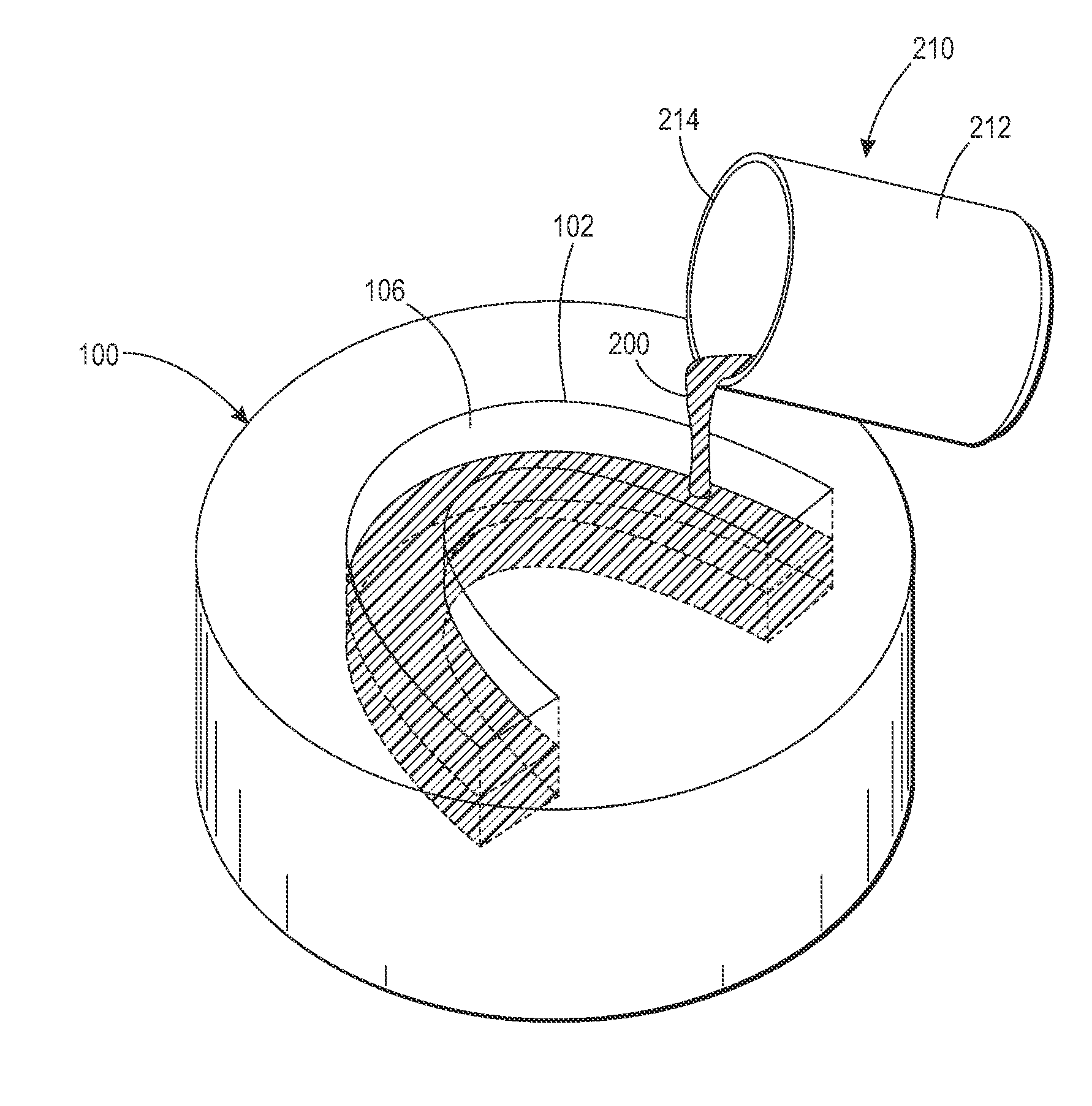
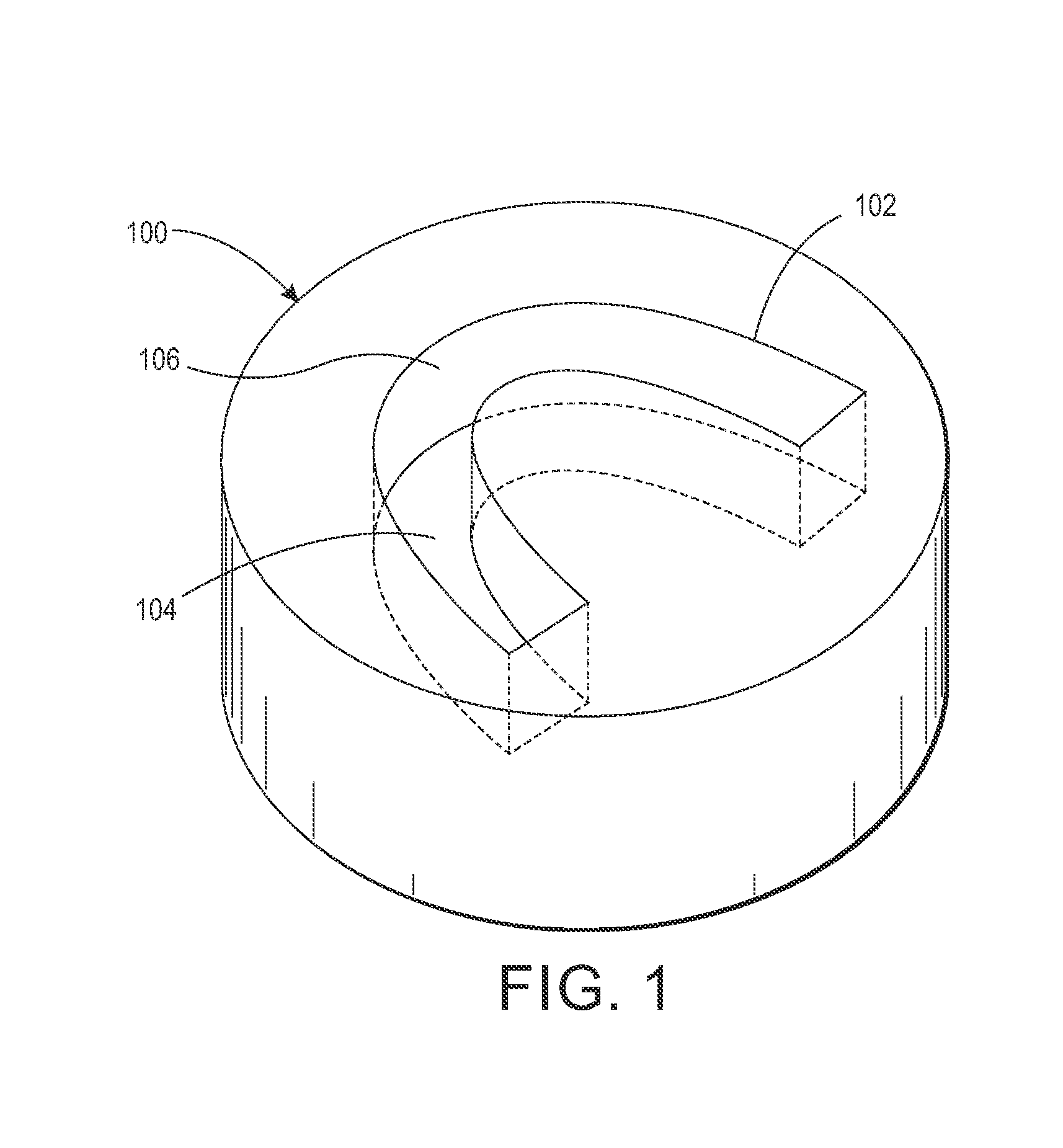
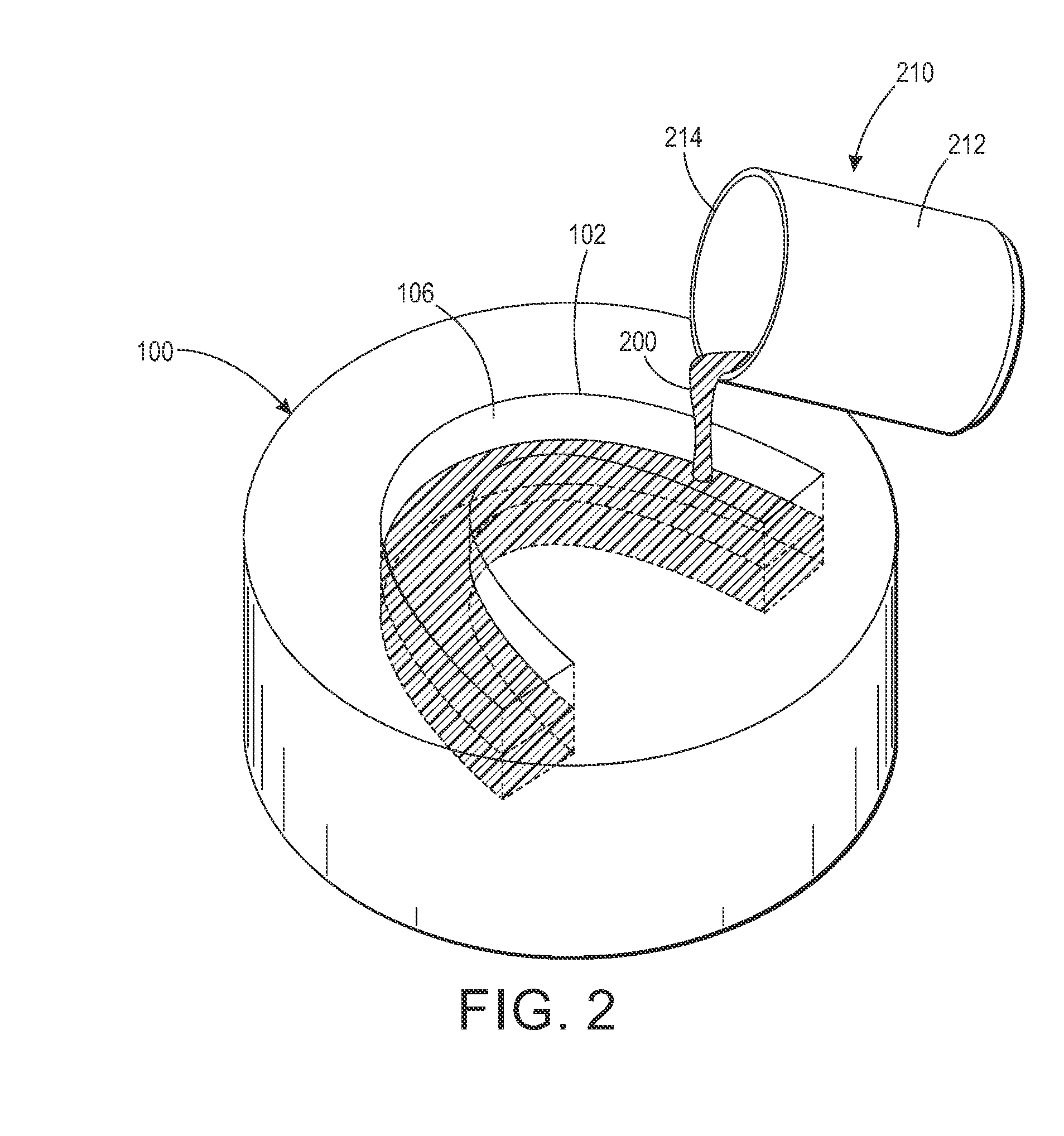
[0050]The Applicant's method and apparatus for molding artificial teeth in a denture base material will now be described with reference to FIGS. 1-7. Turning first to FIG. 1, the instant method comprises forming a first cavity 102 in a block 100 of a denture base material. The first cavity 102 has a bottom wall 104 and a side wall 106. The first cavity is formed to correspond to the U-shaped contour of natural teeth as arranged on maxillae or on a mandible. The first cavity is formed by an apparatus that includes a material removal device (not shown). In certain embodiments, the material removal device may be a mill. The mill may be a mill as disclosed in the aforementioned U.S. Pat. No. 8,641,938 of Howe. In certain embodiments, the width of the U-shaped cavity 102 may be about 0.5 inches wi...


PUM

PropertyMeasurementUnit
temperatureaaaaaaaaaa
depthaaaaaaaaaa
thicknessaaaaaaaaaa

Abstract

A method of molding artificial teeth in denture base material comprising forming a U-shaped cavity in a block of denture base material, forming socket cavities in the bottom of the U-shaped cavity, casting a fluid artificial tooth material into the cavities, and causing the fluid tooth material to solidify into solid artificial tooth material while applying pressure. Causing the solidification may include heating the fluid tooth material. The method may include casting a liquid elastomer into a bottom portion of the U-shaped cavity following forming that cavity and prior to the forming the socket cavities, curing the liquid elastomer into a solid elastomeric cushion, and removing the cushion from the U-shaped cavity. Subsequently, the cushion may be inserted into the U-shaped cavity and contacted with the fluid tooth material. A die may then be contacted with the cushion to apply pressure to it and the fluid tooth material during curing.

Description

CROSS-REFERENCE TO RELATED PATENT APPLICATIONS[0001]This application claims priority from U.S. provisional patent Application No. 61 / 765,368 filed Feb. 15, 2013, the disclosure of which is incorporated herein by reference.BACKGROUND[0002]1. Technical Field[0003]Dental prostheses and apparatus and methods of manufacturing them. In particular, methods of molding artificial teeth in a denture base disc that may be used in computer-implemented (CAD-CAM) methods to form a removable denture. An apparatus for molding artificial teeth in a denture base disc is also disclosed.[0004]2. Description of Related Art[0005]According to current practice, conventional dentures are made by a dental laboratory using a “lost wax” technique. In this technique, a denture base is formed out of wax on a baseplate fitted to a stone model; then plastic denture teeth are fitted into the wax. More wax is added to form interproximal (between the teeth) contours and to make the denture appear life-like. This waxe...

Claims


Application Information

Patent Timeline
Patent Type & Authority Applications(United States)
IPC IPC(8): A61C13/08A61K6/083
CPCA61K6/083A61C13/081A61C13/0022A61C13/04A61C13/10A61K6/887
Inventor MCDERMOTT, RICHARDHOWE, DEVON O.
Owner GLOBAL DENTAL SCI
Why Eureka
Try Eureka