
Methods for simultaneous cardiac substrate mapping using spatial correlation maps between neighboring unipolar electrograms

a mapping method and a technology for cardiac substrates, applied in the field of simultaneous mapping of cardiac substrates, can solve the problems of difficult to determine difficult to locate the best site for ablation, and difficulty in determining the source of an arrhythmia,

Active Publication Date: 2014-08-21
MEDTRONIC INC
View PDF2 Cites 74 Cited by
  • Summary
  • Abstract
  • Description
  • Claims
  • Application Information

AI Technical Summary

Benefits of technology

The present invention provides a method and system for mapping cardiac tissue. This involves recording a base cardiac electrogram signal and simultaneously recording a plurality of cardiac electrogram signals from other electrodes at the same time. These signals are then compared to determine the similarities between them. This information is used to map specific areas of cardiac tissue. Additionally, this invention also provides a method for identifying arrhythmogenic cardiac tissue and treating it with ablation. Overall, this invention improves the accuracy and efficiency of cardiac tissue mapping and treatment.

Problems solved by technology

Unfortunately, locating the best site for ablation has proven to be very difficult, even for the most skilled physicians.
However, the source of an arrhythmia may be difficult to determine based upon the sensed electrogram morphology.
Further, ablation of one or more identified sites may also be problematic.
To date, such ablations require either substantial trial and error (for example, ablation of all sources of complex fractionated electrograms) or the use of separate mapping and ablation devices (complex mapping systems utilizing multielectrode arrays or baskets may be used to identify an ablation site, but cannot also be used to ablate the tissue).
However, in complex electrograms, as in those in patients with atrial fibrillation, the electrogram signals may include several deflections making an accurate real-time determination of target tissue regions cumbersome and ambiguous.

Method used


Image

  • Methods for simultaneous cardiac substrate mapping using spatial correlation maps between neighboring unipolar electrograms
  • Methods for simultaneous cardiac substrate mapping using spatial correlation maps between neighboring unipolar electrograms
  • Methods for simultaneous cardiac substrate mapping using spatial correlation maps between neighboring unipolar electrograms

Examples


Embodiment Construction

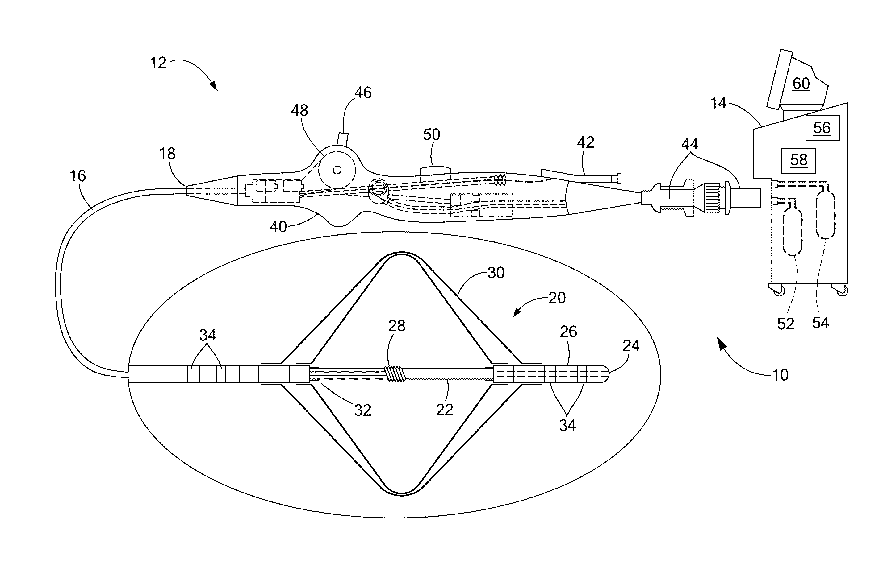
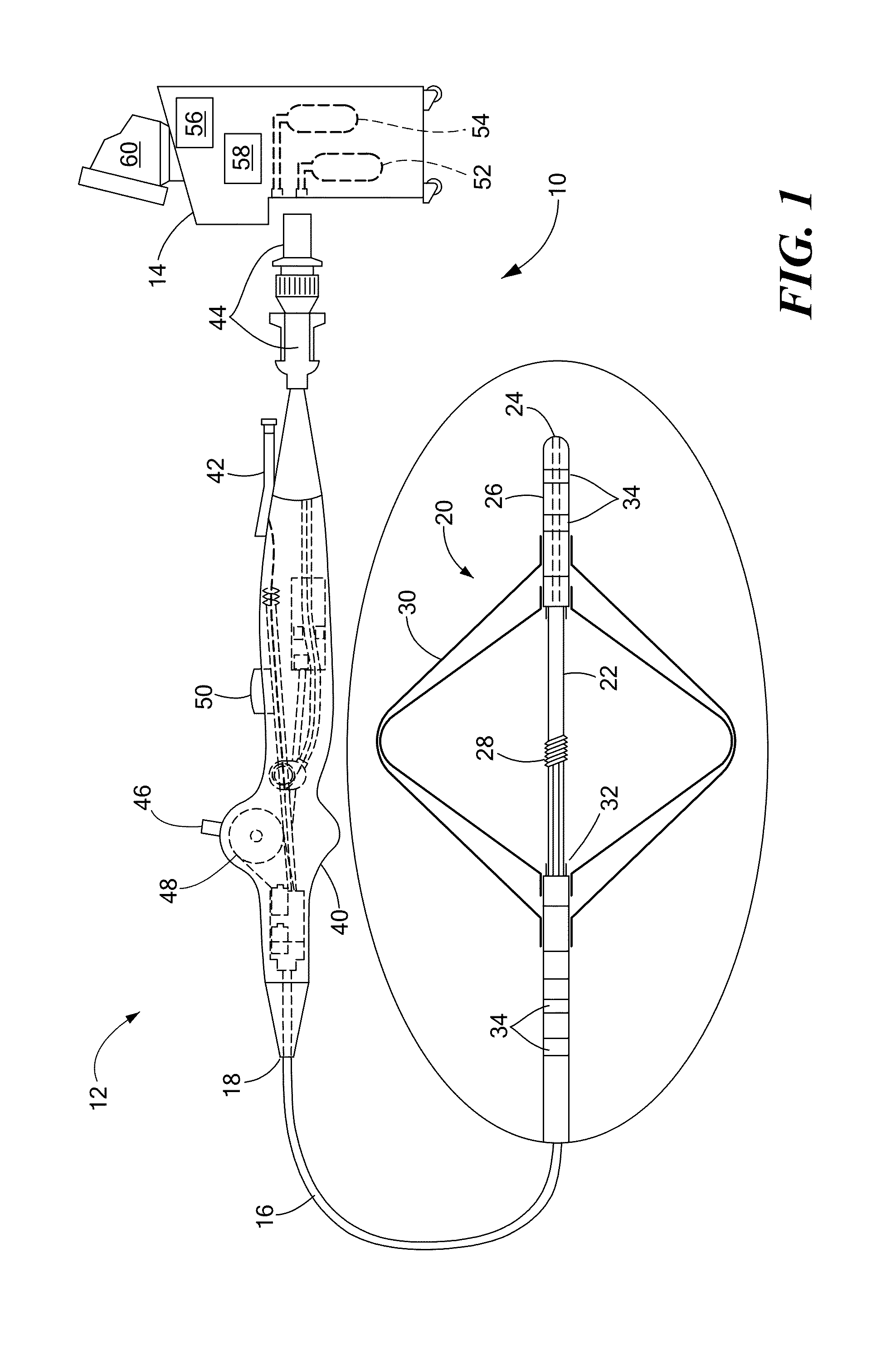
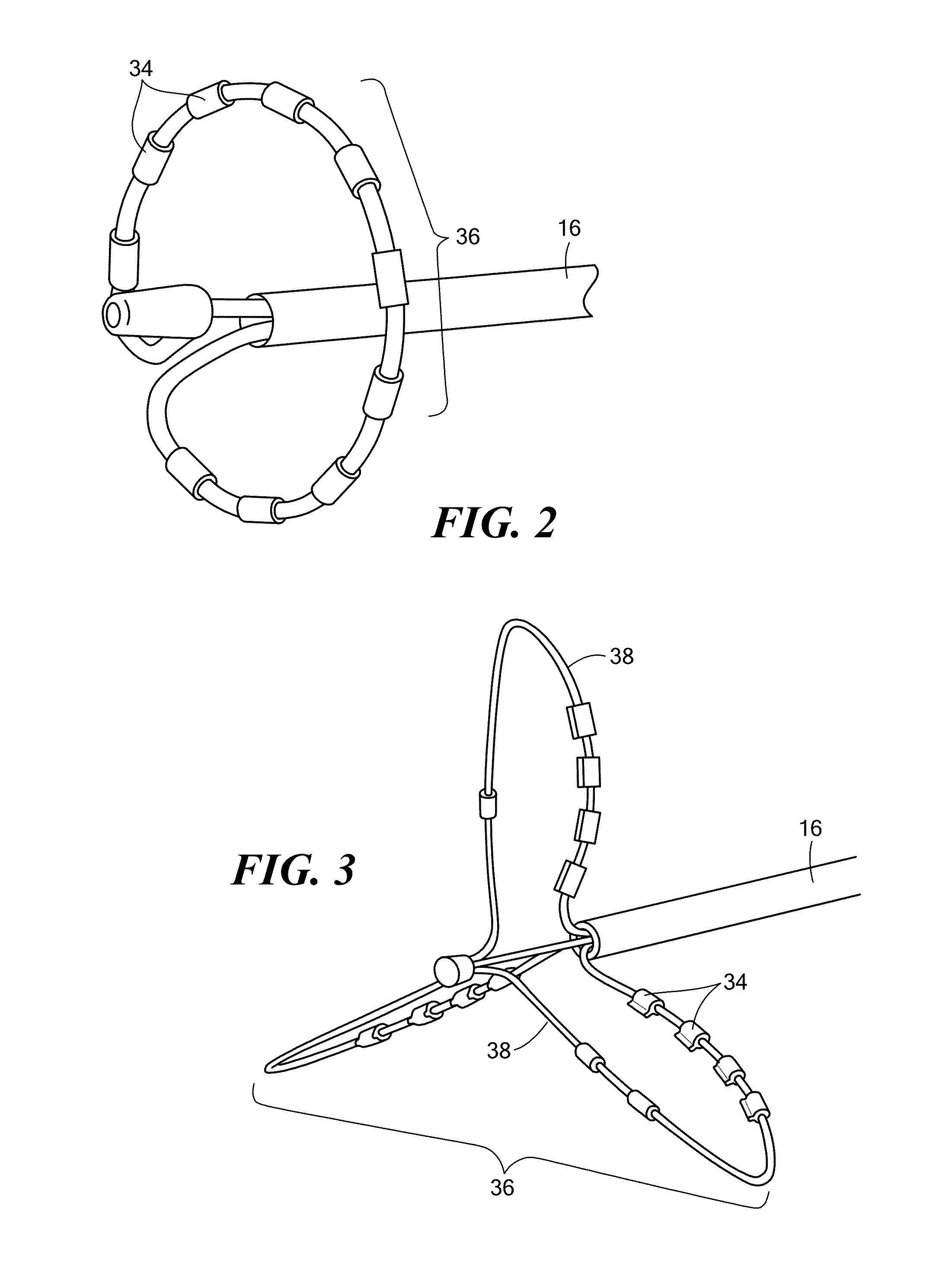
[0024]Substrate mapping, sequential or simultaneous, may be used to identify arrhythmia circuits that are often the targets of ablation. Sequential mapping may involve using a roving catheter probe to record electrical activity, such as potentials, voltages and electrograms, at a time and point within the myocardium, and then moving the catheter to another point to record electrical activity at a different subsequent time. Simultaneous substrate mapping may involve using a multi-electrode basket catheter to record electrical activity simultaneously over multiple points within a region of mapping. The processing of the recorded electrical information helps identify the arrhythmia circuit.

[0025]Conventional mapping involves extracting cardiac activation times by picking up points of deflection or steepest negative slope, and displaying the times over a surface (isochronal map). The patterns during an arrhythmia are observed. For example, an observed pattern may include a rotor around ...


PUM


Abstract

A base cardiac electrogram signal at a base electrode is recorded for a predetermined amount of time. A plurality of cardiac electrogram signals at a plurality of electrodes other than the base electrode are recorded for the predetermined amount of time. The base cardiac electrogram signal is compared with each of the plurality of cardiac electrogram signals. The similarities between the base cardiac electrogram signal and each of the plurality of cardiac electrogram signals is determined. A specific area of cardiac tissue where the base electrode is positioned is mapped based at least in part on the determined similarities.

Description

CROSS-REFERENCE TO RELATED APPLICATION[0001]n / aSTATEMENT REGARDING FEDERALLY SPONSORED RESEARCH OR DEVELOPMENT[0002]n / aFIELD OF THE INVENTION[0003]The present invention relates to a method and system for mapping cardiac substrate.BACKGROUND OF THE INVENTION[0004]A cardiac arrhythmia is a condition in which the heart's normal rhythm is disrupted. There are many types of cardiac arrhythmias, including supraventricular arrhythmias that begin above the ventricles (such as premature atrial contractions (PACs), atrial flutter, accessory pathway tachycardias, atrial fibrillation, and Atrioventricular nodal reentrant tachycardia (AVNRT)), ventricular arrhythmias that begin in the lower chambers of the heart (such as premature ventricular contractions (PVCs), ventricular tachycardia (VT), ventricular fibrillation, and long QT syndrome), and bradyarrhythmias that involve slow heart rhythms and may arise from disease in the heart's conduction system. Further, cardiac arrhythmias may be classif...

Claims


Application Information

Patent Timeline
Patent Type & Authority Applications(United States)
IPC IPC(8): A61B5/042A61B5/0432A61B5/046A61B5/04A61B5/044A61B5/361G16B45/00
CPCA61B5/0422A61B5/04012A61B5/046A61B5/044A61B5/0432A61B5/7246A61B5/316A61B5/287A61B5/349A61N1/05A61B5/333A61B5/339A61B5/361A61B18/12A61B18/1492A61B2018/00214A61B2018/00267A61B2018/00577A61B2018/00839
Inventor GHOSH, SUBHAM
Owner MEDTRONIC INC
Learn More