Methods for discovering, partitioning, organizing, and administering communication devices in a transformer area network

a transformer area network and communication device technology, applied in the field of methods, can solve problems such as limiting the amount of data transmitted

Inactive Publication Date: 2014-08-21
DOMINION ENERGY TECH +1
View PDF25 Cites 46 Cited by
  • Summary
  • Abstract
  • Description
  • Claims
  • Application Information

AI Technical Summary

Benefits of technology

[0040]One method implemented by the Remote Hubs and the Substation Receiver provides for channelizing and modulating current signals transmitted from the at least one Remote Hub in the service area of an electrical distribution substation such that the signals are received at the Substation Receiver and the Substation Receiver is able to infer the electrical phase of the specific feeder upon which the signal was transmitted. The signal is transmitted on a broad band of the frequency spectrum called a channel, but the frequency bands of channels are selected so that the frequency is lower than the low-pass threshold of the service transformer that powers the Edge Transmitter. Several modulation techniques have been used in this context, including frequency spread modulation, Binary Phase-Shift Keying (BPSK), and Quadrature Phase-Shift Keying (QPSK). Higher-order modes of phase-shift keying (mPSK) may be used. However, BPSK and QPSK may be preferred embodiments along with frequency spreading, because higher-order PSKs require more power at the transmitter in order to achieve the same signal strength at the receiver. According to some embodiments of the methods, an Edge Transmitter is capable of encoding at least 80 bits per second of post-FEC (forward error correction) data in a burst transmission at low but adequate current so that the signal is not so significantly attenuated by intermediate transformers, capacitors, long lines, underground wiring, and the like to prevent reception by the Substation Receiver. In other embodiments, an Edge Transmitter may be capable of encoding at lower bit rates. Encoding at lower bit rates improves reliability, but limits the amount of data transmitted. In order to obtain the same post-FEC message success rate while transmitting at at least 80 bps, different modulation types may require different Forward Error Correction rates. The method requires little power to inject the signal, so that the signals as modulated do not radiate energy in the RF spectrum or cause flicker or hum on devices in proximity to the transmissions or exhibit any of the other undesirable characteristics of prior art methods of on-grid messaging. The method works on all the grid topologies described herein above, and can support a sufficient number of Remote Hubs per substation transformer that even the largest substations can be fully covered by the resulting Grid Location Aware™ network.
[0043]In some embodiments of the invention, a number of techniques may be employed for managing channel quality, depending on the availability of Substation-to-Edge broadcast capability from adjacent networks, such as an AMI, AMR, and / or radio broadcast transmitter. Software on the Substation Receivers and Computing Platform may monitor aspects of the channel quality and take measures to ensure that messages from the Remote Hubs experience an acceptably high success rate. According to one aspect of the invention, an acceptably high success rate may be ensured by rotating the responsibilities of the several channels, except that at least one non-structured channel is not rotated but remains dedicated to provisioning and alerting. For example, if two data bearing channels have been identified, and one data bearing channel demonstrates a higher success rate than the other, then the network may be provisioned to have Remote Hubs alternate between transmitting on the better channel and the other channel. This reduces the overall probability of a given Remote Hub experiencing an unacceptably high message failure rate.

Problems solved by technology

Encoding at lower bit rates improves reliability, but limits the amount of data transmitted.

Method used


Image

  • Methods for discovering, partitioning, organizing, and administering communication devices in a transformer area network
  • Methods for discovering, partitioning, organizing, and administering communication devices in a transformer area network
  • Methods for discovering, partitioning, organizing, and administering communication devices in a transformer area network

Examples


Embodiment Construction

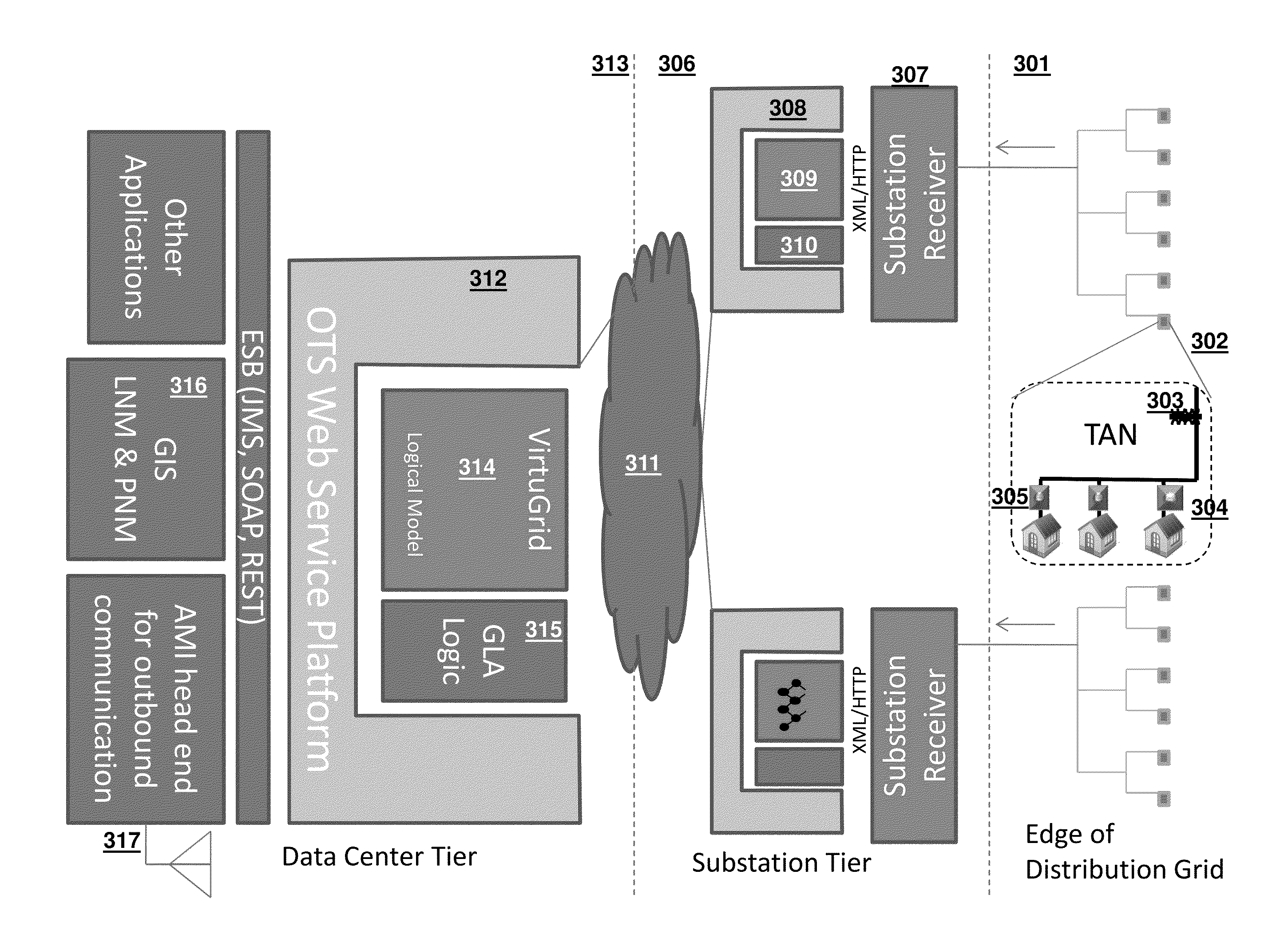
[0073]The present invention comprises a system and methods for constructing and operating an on-grid data collection network in such a way as to integrate the network with other adjacent networks and devices present at the edge, substations, and features of an electrical distribution network, wherein the other networks and devices may include Smart Meters and the AMI and a conventional network such as the Internet. The system and methods further integrate the data collected by the on-grid data collection network at a data center and may publish the collected data to other applications. The system and methods may also employ the capabilities of the integrated networks to infer otherwise unknown static and transient attributes of the electrical distribution grid and report them via the integrated networks for the purpose of improving the physical and logical network models of the Smart Grid. This leads to the ability of the models to support Smart Grid applications such as conservatio...


PUM


Abstract

A system and methods for managing a transformer area in an electrical distribution grid having at least one substation transformer and one service transformer are presented. At least one Remote Hub governed by a policy may be provided, which collects data about the transformer area. The Remote Hub may also execute a discovery procedure to inventory Remotes in the transformer area. The Remote Hub may use the collected data to detect events, such as exceptional conditions, configuration changes, or derived results, within the transformer area. Based on the collected data, the Remote Hub is able to transmit data about the transformer area via a Substation-to-Edge channel. A method and system for forming and establishing boundaries of Transformer Area Networks is also presented. Discovery procedures may be used to form Transformer Area Networks out of Remote Hubs and Remotes powered by the same phase of the service transformer.

Description

RELATED APPLICATIONS[0001]This application claims priority to U.S. Provisional Application No. 61 / 766,551, filed on Feb. 19, 2013, and U.S. Provisional Application No. 61 / 779,222, filed on Mar. 13, 2013, the contents of which are incorporated herein by reference.FIELD OF THE INVENTION[0002]The present invention is directed toward employing the electrical distribution grid as a short and long-range transmission medium and data-bearing network, and further toward the use of signals and messages on the network for the purpose of inferring schematic and topological properties of the distribution grid, which vary over time.BACKGROUND OF THE INVENTION[0003]The power grid is generally considered to be composed of two logical regions, the Transmission Grid(s) and the Distribution Grid(s). The Transmission Grid originates at large generation points such as hydroelectric dams, nuclear reactors, wind farms, and coal-fired or gas-fired power plants. Power from the generation point is transmitte...

Claims


Application Information

Patent Timeline
Patent Type & Authority Applications(United States)
IPC IPC(8): G05B13/02
CPCG05B13/02H04B2203/5433H04B3/546H04L41/083H04L43/0847H04L1/0009H04L1/188G06Q50/06H04B2203/5466Y04S40/121H04B3/54H02J13/00007H02J13/00034Y04S40/00Y02E60/00H04L41/0803Y04S10/16H04B3/542H04L41/12G01R29/18
Inventor MARTIN, MARCIA REIDBERNHEIM, HENRIK F.HANSELL, JERRITTLUCAS, MICHAEL ALAN
Owner DOMINION ENERGY TECH
Why Eureka
Try Eureka