Ventilation Tube System

a technology of ventilation tube which is applied in the direction of respirator, electrical apparatus, ohmic resistance heating, etc., can solve the problems of increased clutter in the patient environment, loss of time, and operator confusion, so as to reduce the danger of infection for patients, increase the reliability of measurement and tube heating function, and avoid contamination

Active Publication Date: 2014-08-28
HAMILTON MEDICAL AG
View PDF8 Cites 12 Cited by
  • Summary
  • Abstract
  • Description
  • Claims
  • Application Information

AI Technical Summary

Benefits of technology

[0012]wherein at least certain portions of the first inhalation tube and the exhalation tube each comprise tube heaters having at least one heating wire, wherein each of the tube heaters is controllable by a power supply and control unit inside the respiratory humidifier. The ventilation tube system is characterized in that a power supply line for the tube heater of the exhalation tube starts from a link of the second inhalation tube at the respiratory humidifier and proceeds from there via the second inhalation tube and a connecting element separate from the respirator. As a result of the high degree of integration of the electrical lines into the pneumatic tube connections, the ergonomics are significantly improved for the user, for the possibility of operator error and technical defects is reduced. In addition, fewer tubes and cables are exposed, as a result of which the overall system takes up less space and is less vulnerable to malfunction.
[0024]Also according to an aspect of the invention is a ventilation system comprising a respirator, a respiratory humidifier, and a ventilation tube system as described above, wherein the respiratory humidifier comprises a control unit serving to supply the current and to control the tube heaters for the exhalation tube and the first inhalation tube. As previously mentioned, the humidity and the temperature of the breathing gas are usually adjusted by the respiratory humidifier. This offers the advantage to the user that any suitable respirator can be used to make the breathing gas available, and the function of breathing air humidification and its control can take place in the respiratory humidifier, independently of the respirator.

Problems solved by technology

The disadvantage of these ventilation tube systems according to the prior art is that, in addition to the pneumatic connections of the inhalation and exhalation tubes to the respirator, respiratory humidifier, and the Y-piece on the patient, it is also necessary to connect the electrical lines for the tube heater and the temperature sensor, which are present as loose, independent cables and which must be connected independently of each other.
The large number of cables and tubes to be connected leads to a loss of time and to the possible confusion of the operator; it also increases the clutter in the patient environment, and the various components are also vulnerable to damage.
The use of such loose cables also carries with it the danger that the operator or the patient could become tangled up in them, which, in the worst possible case, could result in the breaking-off of the electrical connection between the respiratory humidifier and the heating wires during the treatment of the patient.

Method used


Image

  • Ventilation Tube System
  • Ventilation Tube System
  • Ventilation Tube System

Examples


Embodiment Construction

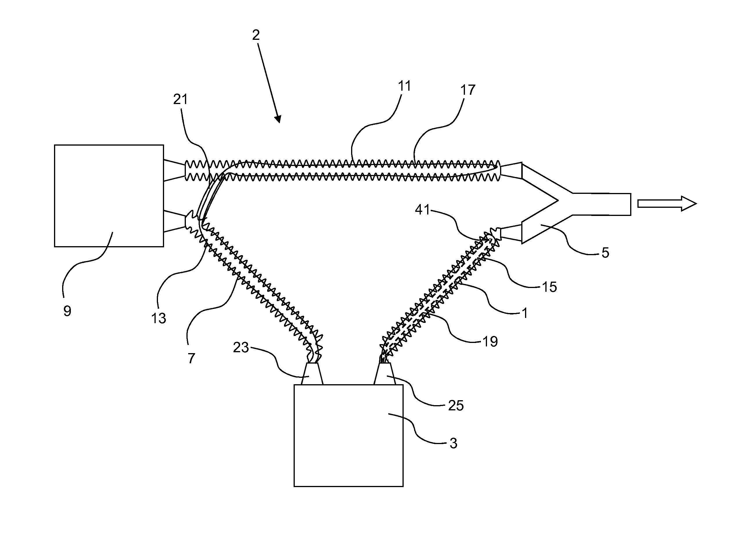
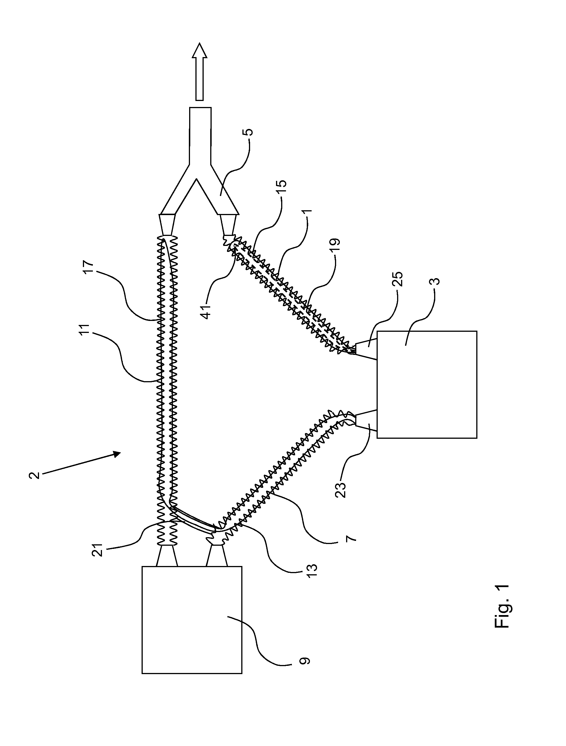
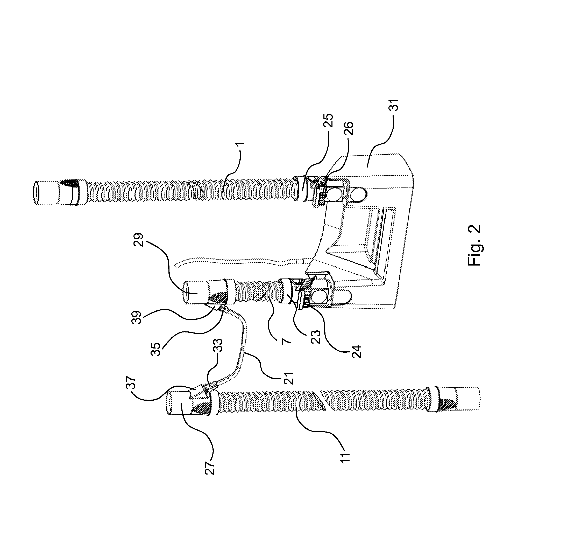
[0029]FIG. 1 shows a schematic diagram of a preferred embodiment of an ventilation tube system according to the invention. A first inhalation tube 1 is arranged between a respiratory humidifier 3 and a Y-piece 5. The simply designed end of the Y-piece 5 is directed toward the patient to be ventilated, as indicated by the arrow. A second inhalation tube 7 connects the respiratory humidifier 3 to the respirator 9. Finally, an exhalation tube 11 is arranged between the respirator 9 and the remaining end of the Y-piece 5.

[0030]Dry breathing gas is produced in the respirator 9 by, for example, a blower (not shown) and leaves through the second inhalation tube 7, proceeding toward the respiratory humidifier 3. There the breathing gas is conducted in the known manner into a liquid container 31 (not shown in FIG. 1), where it is heated and humidified by the heated liquid. The heated and humidified breathing gas leaves the breathing gas humidifier through the first inhalation tube and reache...


PUM


Abstract

A ventilation tube system for breathing gas for ventilating patients is provided, the system having a first inhalation tube (1) connectable to a respiratory humidifier (3) and to a Y-piece (5); a second inhalation tube (7) connectable to a respirator (9) and to the respiratory humidifier (3); and an exhalation tube (11) connectable to the respirator (9) and to the Y-piece (5); wherein at least certain portions of the first inhalation tube (1) and the exhalation tube (11) each comprise tube heaters having at least one heating wire (15, 17) wherein each of the tube heaters is controllable by a power supply and control unit inside the respiratory humidifier (3) wherein a power supply line (13) of the tube heater of the exhalation tube (11) starts from a link of the second inhalation tube (7) at the respiratory humidifier (3) and proceeds from there via the second inhalation tube (7) and a connecting element (21) separate from the respirator (9).

Description

FIELD OF INVENTION[0001]The present invention pertains to a ventilation tube system for ventilating patients with breathing gas and to a ventilation system comprising a respirator, a respiratory humidifier, and a ventilation tube system.BACKGROUND OF THE INVENTION[0002]When patients are being ventilated mechanically on an intensive-care ward, for example, the patient to be ventilated is connected pneumatically to the respirator by means of a ventilation tube system. Because the breathing gas which is delivered to the patient must be adjusted with respect to temperature and humidity to the physiological needs of the patient, a respiratory humidifier is arranged in the inhalation or inspiration tube to heat and humidify the breathing gas. The breathing gas humidifier comprises a liquid container filled with distilled water in the usual manner; the inhalation gas is conducted through this container, and its moisture content is thus increased.[0003]To prevent moisture from condensing in...

Claims


Application Information

Patent Timeline
Patent Type & Authority Applications(United States)
IPC IPC(8): A61M16/10A61M16/08A61M16/16
CPCA61M16/1095A61M16/16A61M16/0833
Inventor BUECHI, RUDOLFFREI, RETOMAEDER, MARCGRANZOTTO, THOMASZOLKOS, AXEL
Owner HAMILTON MEDICAL AG
Why Eureka
Try Eureka