Electronic part and electronic control unit

a technology of electronic control unit and electronic part, which is applied in the direction of printed circuit aspects, high current circuit adaptations, printed circuit non-printed electric components association, etc., can solve the problems of difficult to make a size of printed board and electronic control unit, difficult to commonalize or standardize printed boards for different types of electronic control units, and difficult to simply change electronic parts. , to achieve the effect of preventing reconnection, reducing the width and ensuring stability

Active Publication Date: 2014-08-28
DENSO CORP +1
View PDF5 Cites 5 Cited by
  • Summary
  • Abstract
  • Description
  • Claims
  • Application Information

AI Technical Summary

Benefits of technology

[0038]According to the above feature, it is possible to stably support the main body at the position above and separated from the board surface by the second leg portion of the fuse terminal and the normal terminal, even in a case that the cut-off portion is melted down. Accordingly, it is possible to prevent re-connection between the electrode and the land.
[0039]Since the cut-off portion has the smaller width than the other portions of the fuse terminal, the cut-off portion is easily deformed when any external force is applied to it. However, according to the above feature of the present disclosure, the fuse terminal has the second leg portion in addition to the first leg portion of the electrical path portion. As a result, it is possible to prevent a possible deformation of the cut-off portion, which may be caused by contact with a jig when the fuse terminal is mounted to the printed board and / or during a transportation process after the product is completed. Accordingly, it is possible that the cut-off portion brings out its function for cutting off the electrical connection between the electrode and the land.
[0040]Furthermore, according to the above feature, the second leg portion is separately formed from the first leg portion of the electrical path portion by the slit. When compared the fuse terminal having the second leg portion with such a fuse terminal having no second leg portion, a width of the large-width portion of the fuse terminal having the second leg portion is smaller than that of the fuse terminal having no second leg portion, in a condition that a maximum width of the fuse terminal having the second leg portion is equal to that of the fuse terminal having no second leg portion. Therefore, it is possible to make smaller an amount of heat of the cut-off portion, which may go away to other portions of the electrical path portion. In addition, since a space is formed between the first leg portion for the electrical path portion and the second leg portion, the heat of the cut-off portion is hardly transmitted to the second leg portion. As above, it is possible to prevent the heat of the cut-off portion from going away to the other portions of the fuse terminal, and the response is thereby improved.

Problems solved by technology

As a result, it is difficult to commonalize or standardize the printed boards for different types of electronic control units.
In other words, it is difficult to commonalize the printed boards and to simply change the electronic parts to be mounted to the printed board in order to use the same type of the printed board for the different types of the electronic control units (variation products).
In addition, it is difficult to make a size of the printed board as well as the electronic control unit smaller, because the pattern fuse (or pattern fuses) is formed in the printed board as a part of the wiring patterns.
Since the heat of the pattern fuse goes away to the insulating board as above, it is a problem that it may take a longer time from short-circuit in the electronic part to melt-down of the pattern fuse.
In other words, it is not possible to quickly cut off the pattern fuse with high response.
In addition, since response characteristics vary, it is not possible to assure accuracy of performance for cutting off the pattern fuse.

Method used


Image

  • Electronic part and electronic control unit
  • Electronic part and electronic control unit
  • Electronic part and electronic control unit

Examples


first embodiment

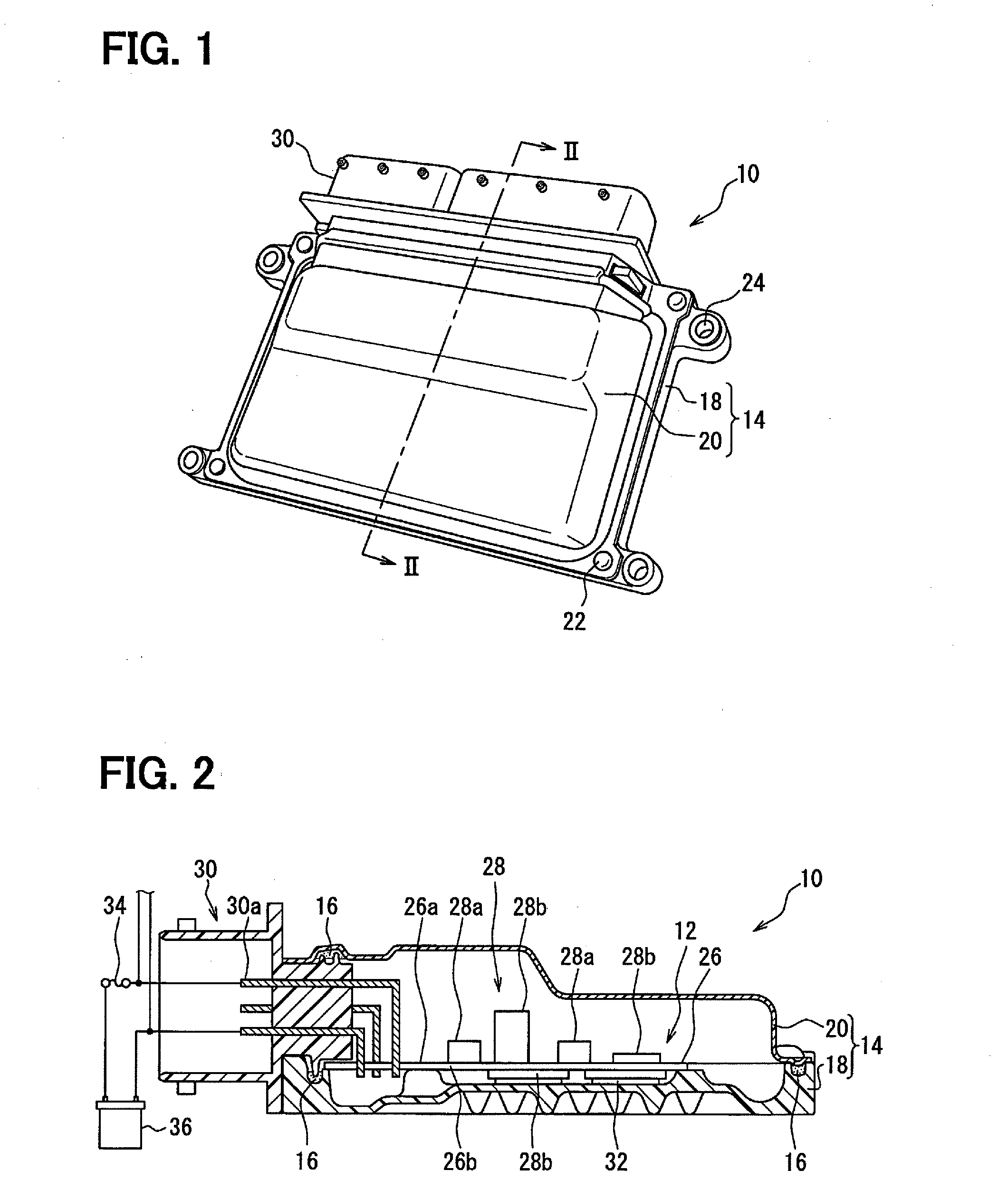
[0052]An electronic control unit 10 shown in FIGS. 1 and 2 has a circuit board 12 as a main part thereof. The electronic control unit 10 further has a housing 14 for accommodating the circuit board 12 and a seal element 16. In the present embodiment, the electronic control unit 10 is formed as an electronic control unit (ECU) of a water-proof type for controlling an operation of an engine for a vehicle.

[0053]An outline structure for the electronic control unit 10 will be hereinafter explained.

[0054]The housing 14 is made of metal, such as, aluminum, iron or the like, or resin material, for accommodating therein the circuit board 12 so as to protect the same from water, dust and so on. A number of parts for forming the housing 14 is not limited to a specific number, so that the housing 14 may be composed of one or multiple members.

[0055]As shown in FIG. 2, according to the present embodiment, the housing 14 is composed of two parts, that is, a lower casing 18 of a shallow-box shape h...

second embodiment

[0095]A second embodiment of the present disclosure will be explained with reference to FIGS. 7 and 8. Explanation for those portions, which are similar to or the same to those of the first embodiment (including the electronic part 28a, the electronic control unit 10 and so on), will be omitted.

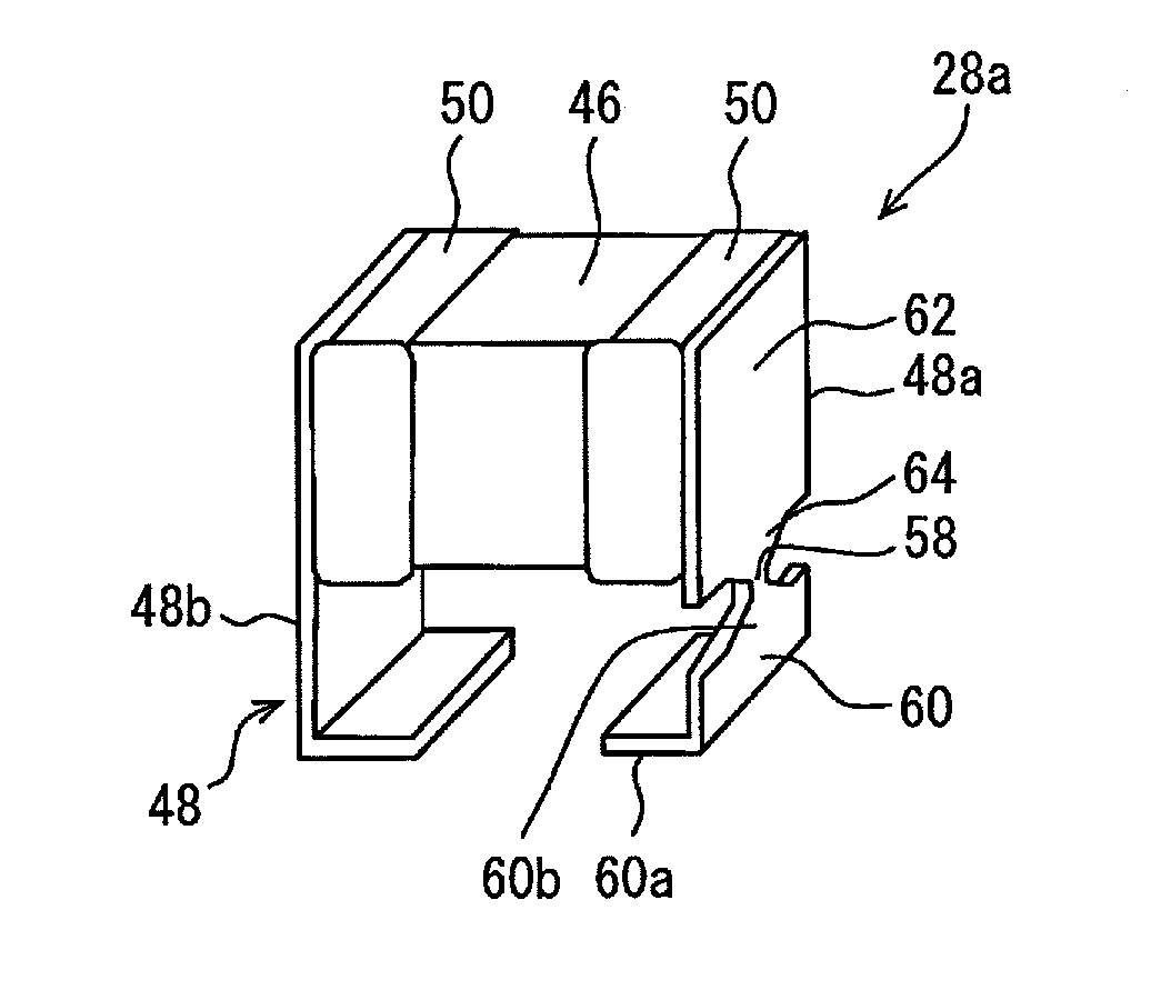
[0096]As shown in FIG. 7, the fuse terminal 48a has multiple slits 66 extending in a direction from a lower end thereof on the side of the surface-mounted portion 60a toward the electrode-connected portion 62a, wherein each of the slits 66 has a predetermined length. Multiple leg portions 68 and 70 of a forked shape are formed by the slits 66.

[0097]In the present embodiment shown in FIG. 7, the fuse terminal 48a has two slits 66 and three leg portions 68 and 70. One of the leg portions (a first leg portion 68) located at a center forms the electrical path portion 56. The other two leg portions 70 at both sides of the electrical path portion 56 (the first leg portion 68) form second leg portio...


PUM


Abstract

A main body of an electronic part has multiple electrodes, to which multiple terminals are respectively connected. The terminals include a normal terminal and a fuse terminal, each of which extends from lands formed in a printed board so as to hold the main body at a position above and separated from a board surface of the printed board. The fuse terminal has multiple leg portions divided by slits. A first leg portion forms an electrical path portion having a cut-off portion, a width of which is smaller than that of other portions of the electrical path portion. A second leg portion has a first supporting leg and a second supporting leg, which are arranged at both sides of the first leg portion. Each of the supporting legs is connected to each of dummy lands formed in the printed board.

Description

CROSS REFERENCE TO RELATED APPLICATION[0001]This application is based on Japanese Patent Application No. 2013-038359 filed on Feb. 28, 2013, the disclosure of which is incorporated herein by reference.FIELD OF TECHNOLOGY[0002]The present disclosure relates to an electronic part mounted to a printed board and an electronic control unit having the electronic part.BACKGROUND[0003]A printed board having a pattern fuse, which is a part of wiring patterns formed in the printed board, is known in the art, for example, as disclosed in Japanese Patent Publication No. 2007-311467.[0004]The pattern fuse is generally so formed as to be narrower than a remaining part of the wiring patterns. Therefore, for example, when a short-circuit occurs in an inside of an electronic device or an electronic part and thereby excess current flows, the pattern fuse is melted down due to heat generation in order that an electric pathway is cut off.[0005]In a case of the pattern fuse, it is necessary to individua...

Claims


Application Information

Patent Timeline
Patent Type & Authority Applications(United States)
IPC IPC(8): H01H85/02H05K1/18
CPCH01H85/0241H05K1/18H01H85/10H01H2085/0275H01H2085/2085H05K1/0263H05K1/181H05K3/3426H05K2201/10181H05K2201/10946
Inventor ITABASHI, TORUMIKAMI, YUKISHIRAISHI, RYOICHIYANAGISAWA, AKIHIRONISHIYAMA, SHIGEKI
Owner DENSO CORP
Why Eureka
Try Eureka