Non-contact power supply device

a power supply device and non-contact technology, applied in the direction of charging stations, electric vehicle charging technology, transportation and packaging, etc., can solve the problems of coupling coefficient and power factor reduction, and achieve the effect of suppressing the reduction of a power factor

Active Publication Date: 2014-08-28
NISSAN MOTOR CO LTD
View PDF1 Cites 11 Cited by
  • Summary
  • Abstract
  • Description
  • Claims
  • Application Information

AI Technical Summary

Benefits of technology

[0007]According to the present invention, even if a coupling coefficient is varied, a variation width of a phase of the impedance viewed from an output side of the alternating current power supply with respect to the fundamental wave frequency (f0) is small. As a consequence of this, a reduction in a power factor can be suppressed.

Problems solved by technology

However, since the values of these capacitors are set with a prerequisite such that a coupling coefficient between the primary winding and the secondary winding is constant so as to achieve a high efficiency, such a problem that a power factor is reduced in a case where the coupling coefficient is varied.

Method used


Image

  • Non-contact power supply device
  • Non-contact power supply device
  • Non-contact power supply device

Examples


first preferred embodiment

[0045]As an example of a non-contact power supply device in the preferred embodiment, the non-contact power supply device used together with a vehicle battery and a power load of an electric automotive vehicle or so forth will be described below.

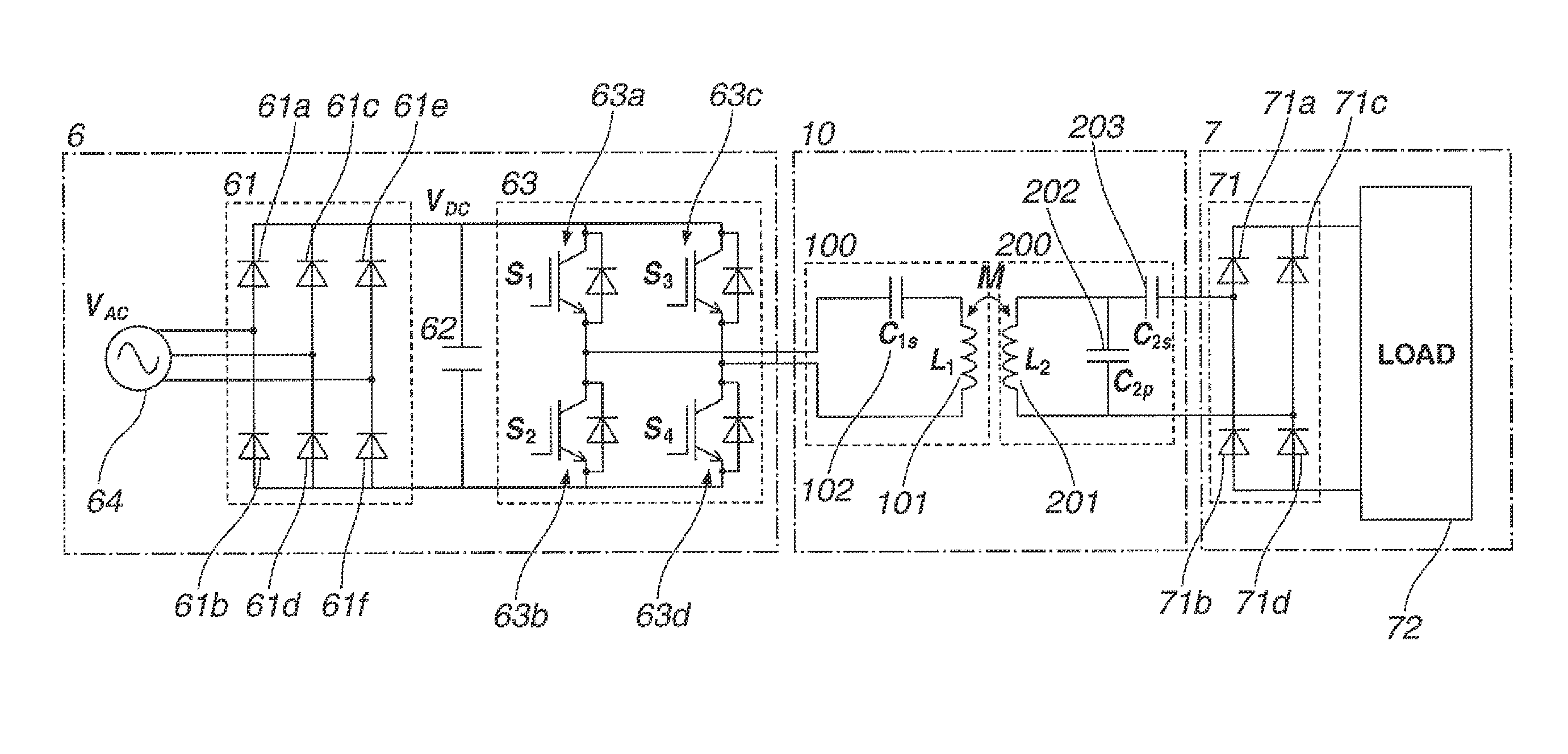
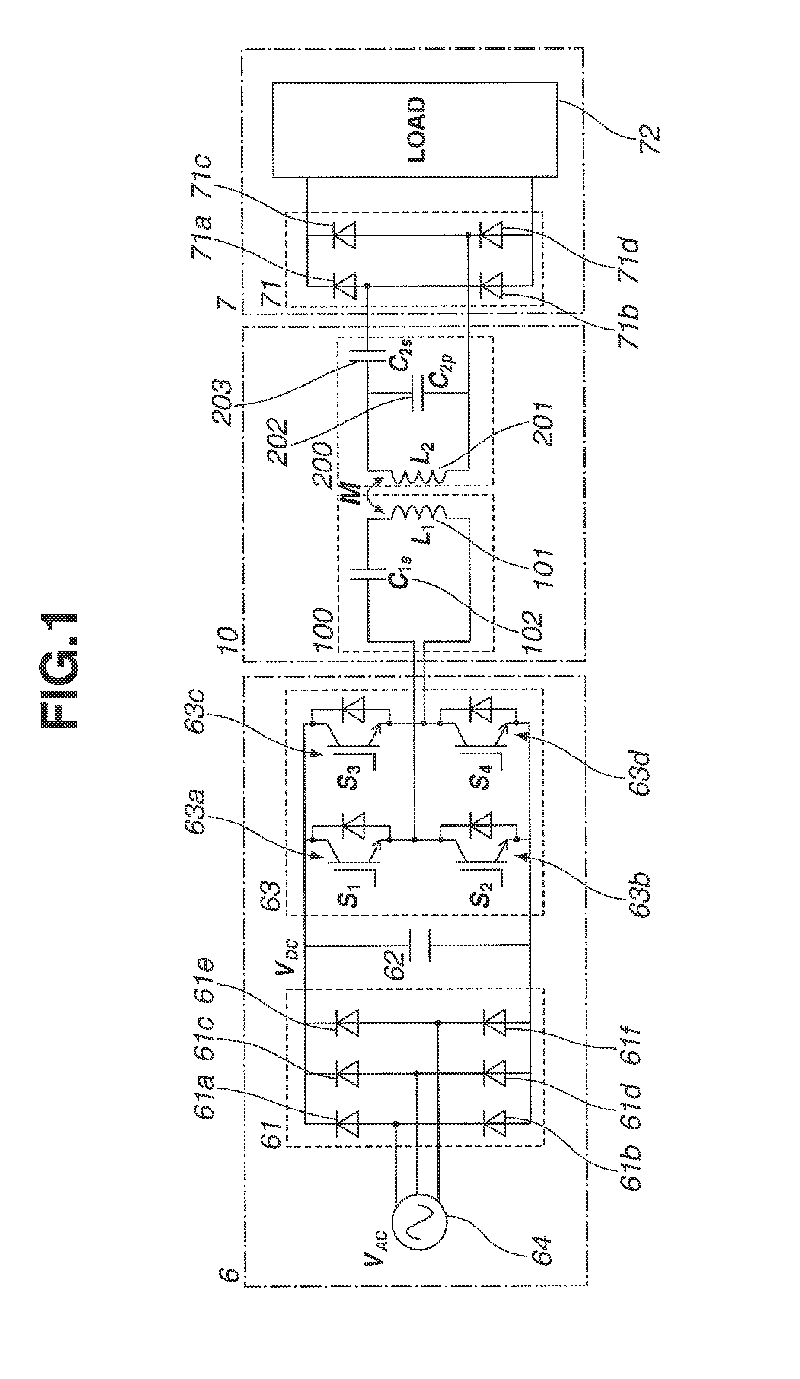
[0046]FIG. 1 shows an electrical circuit diagram of a non-contact power supply device in a first preferred embodiment. The non-contact power supply device in this embodiment includes: a high-frequency alternating current power supply 6; a non-contact (or contactless) power supply section 10 performing a non-contact (contactless) power supply for an electric power outputted from high-frequency alternating current power supply 6; and a load section 7 to which an electric power is supplied by means of non-contact power supply section 10.

[0047]High-frequency alternating current power supply 6 includes: a three-phase alternating current power supply 64; a rectifier 61 rectifying a three-phase alternating current into a direct current; and a volta...

second preferred embodiments

[0085]FIG. 18(a) shows an absolute value characteristic of the impedance (Z1) of the non-contact power supply section of the non-contact power supply device related to a second preferred embodiment according to the present invention. FIG. 18(b) shows another absolute value characteristic of the impedance (Z2) thereof. A difference point of the second embodiment from the first embodiment is that the resonance frequency (f2) is set within a range of a half-value width of the resonance frequency (f1). The other structures of the second embodiment are the same as those of the first embodiment. Thus, the description of the first embodiment is appropriately applied to the description of the second embodiment.

[0086]As shown in FIG. 18 (a), the fundamental wave frequency (f0) of alternating current power supply 64 is set in the proximity of resonance frequency (f1) at which the minimal value of impendance (Z1) is provided. Δf denotes a half-value width of the frequency (f1). Suppose that an...

third preferred embodiment

[0103]FIG. 23 is a circuit diagram representing an equivalent circuit of the non-contact power supply section of the non-contact power supply device in a third preferred embodiment according to the present invention. The difference point of the third embodiment from the first embodiment is that, according to the characteristic of a zero (point) of the input impedance (Zin), the circuit structure of the non-contact power supply device is prescribed. The other structures in this embodiment is the same as those in the first embodiment. Hence, the description of the first and second embodiments is appropriately applied to the description of the third embodiment).

[0104]As shown in FIG. 23, a resistor (R) as an equivalent load resistance of load section 7 is connected to the output side of non-contact power supply section 10, Then, on a basis of the circuit shown in FIG. 23, the impedance characteristic (Zin) viewed from the output side of high-frequency alternating current power supply 6...


PUM


Abstract

A non-contact power supply device comprises: a primary winding (101); and a secondary winding (201) to which an electric power is supplied from an alternating current power supply via the primary winding, wherein an impedance characteristic of Z1 with respect to a frequency is such that a minimal value is provided in the proximity of a frequency of a fundamental wave component of the alternating current power supply and another impedance characteristic of Z2 with respect to the frequency is such that the frequency of the fundamental wave component is provided between the frequency which is nearest to the frequency of the fundamental wave component and at which a maximal value is provided and the frequency which is nearest to the frequency of the fundamental wave component and at which the minimal value is provided.

Description

TECHNICAL FIELD[0001]The present invention relates to a non-contact power supply device.BACKGROUND ART[0002]A previously proposed non-contact power supply device in which a serial capacitor is connected to a primary winding driven by means of an alternating current power supply, a parallel capacitor is connected to a secondary winding, and values of these capacitors are set on a basis of a mathematical equation disclosed in Patent Document 1 described below so that this transformer is substantially equivalent to an ideal transformer is known (Patent Document 1).[0003]However, since the values of these capacitors are set with a prerequisite such that a coupling coefficient between the primary winding and the secondary winding is constant so as to achieve a high efficiency, such a problem that a power factor is reduced in a case where the coupling coefficient is varied.Pre-Published Document[0004]Patent Document 1: Japanese Patent No. 4,644,827DISCLOSURE OF THE INVENTION[0005]It is, t...

Claims


Application Information

Patent Timeline
Patent Type & Authority Applications(United States)
IPC IPC(8): H04B5/00
CPCH04B5/0037B60L2210/10B60L2210/30B60L2210/40B60L53/122B60L53/126B60L53/36H02J50/10Y02T10/70Y02T10/7072Y02T10/72Y02T90/12Y02T90/14H02J50/12
Inventor KAI, TOSHIHIROYAMAUCHI, YUYAKRAISORN, THRONGNUMCHAIMINAGAWA, YUUSUKE
Owner NISSAN MOTOR CO LTD
Why Eureka
Try Eureka