Composite permanent magnet synchronous machine

a permanent magnet synchronous machine and permanent magnet technology, applied in the direction of rotating magnet synchronous machines, dynamo-electric machines, electrical apparatus, etc., can solve the problems of increasing carbon dioxide emissions, thermal power generation may place a great burden on the environment, and the shortcoming of nuclear power generation is the need for processing nuclear waste, so as to reduce manufacturing costs, wide application range, and more flexibility in us

Active Publication Date: 2013-03-21
NAT TAIWAN UNIV OF SCI & TECH
View PDF5 Cites 5 Cited by
  • Summary
  • Abstract
  • Description
  • Claims
  • Application Information

AI Technical Summary

Benefits of technology

[0019]The composite permanent magnet synchronous machine is suitable for use in not only a wind power generator, but also any kind of machine structures. In the meantime, the machine structure provides more flexibility in use due to the property thereof, which is able to switch to three-phase, six-phase, or nine-phase based on the actual requirement. Furthermore, since the machine structure of the present invention can also be used for constructing machine structures with three-phase, six-phase, or nine-phase, capabilities, the same mold can be used for fabricating them, so as to possess a wide application range, and further to decrease the manufacturing cost.

Problems solved by technology

However, thermal power generation may place a great burden on the environment, such as increased carbon dioxide emissions or the high probability of acid rain.
However, a severe shortcoming of nuclear power generation is the need of processing nuclear waste.
Although the radioactivity will decrease gradually, nuclear waste generated by nuclear power generation has to be stored for a long time, even up to thousands of years.
In a wind power generation system, the current harmonic at the generator side is very high, which may cause undesired effects on the generator.
For example, the mechanical efficiency is decreased, and the harmonic frequency is likely to cause core loss and copper loss, resulting in over heating, noise production, and mechanical vibration or similar problems on generators.
Therefore, how to reduce the current harmonic at the generator side and increase the efficiency are major issues to be improved in wind power generation systems or even all other power generation systems.
However, the prior three-phase machine structure is unable to satisfy the actual requirement due to the development of technology and the increased electricity consumption rate.
However, the machine structure capable of switching between three-phase and six-phase cannot meet the requirements for industries, which desire an innovative machine structure.

Method used


Image

  • Composite permanent magnet synchronous machine
  • Composite permanent magnet synchronous machine
  • Composite permanent magnet synchronous machine

Examples


embodiment 1

38 Poles 36 Slots Permanent Magnet Synchronous Machine Module

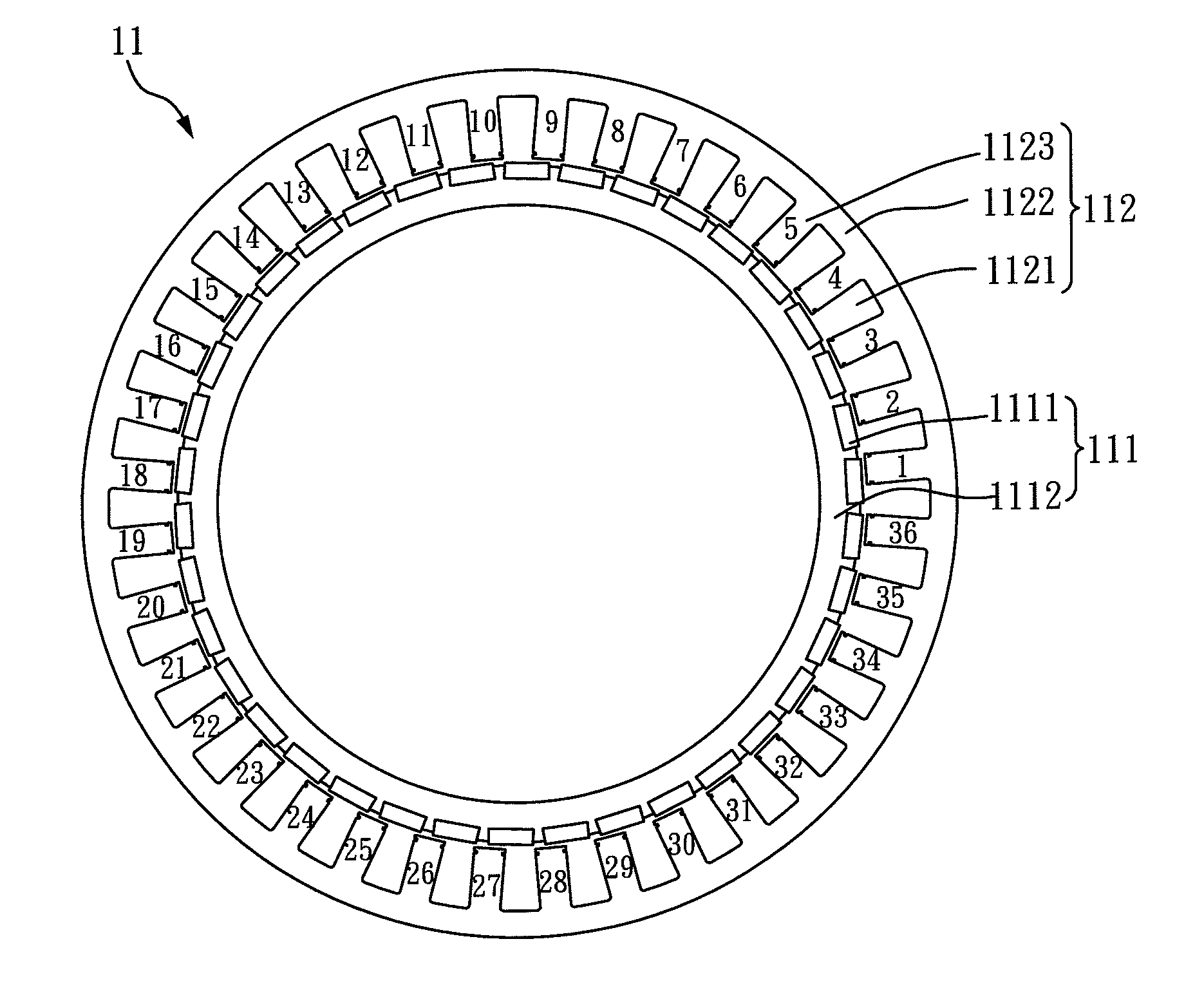
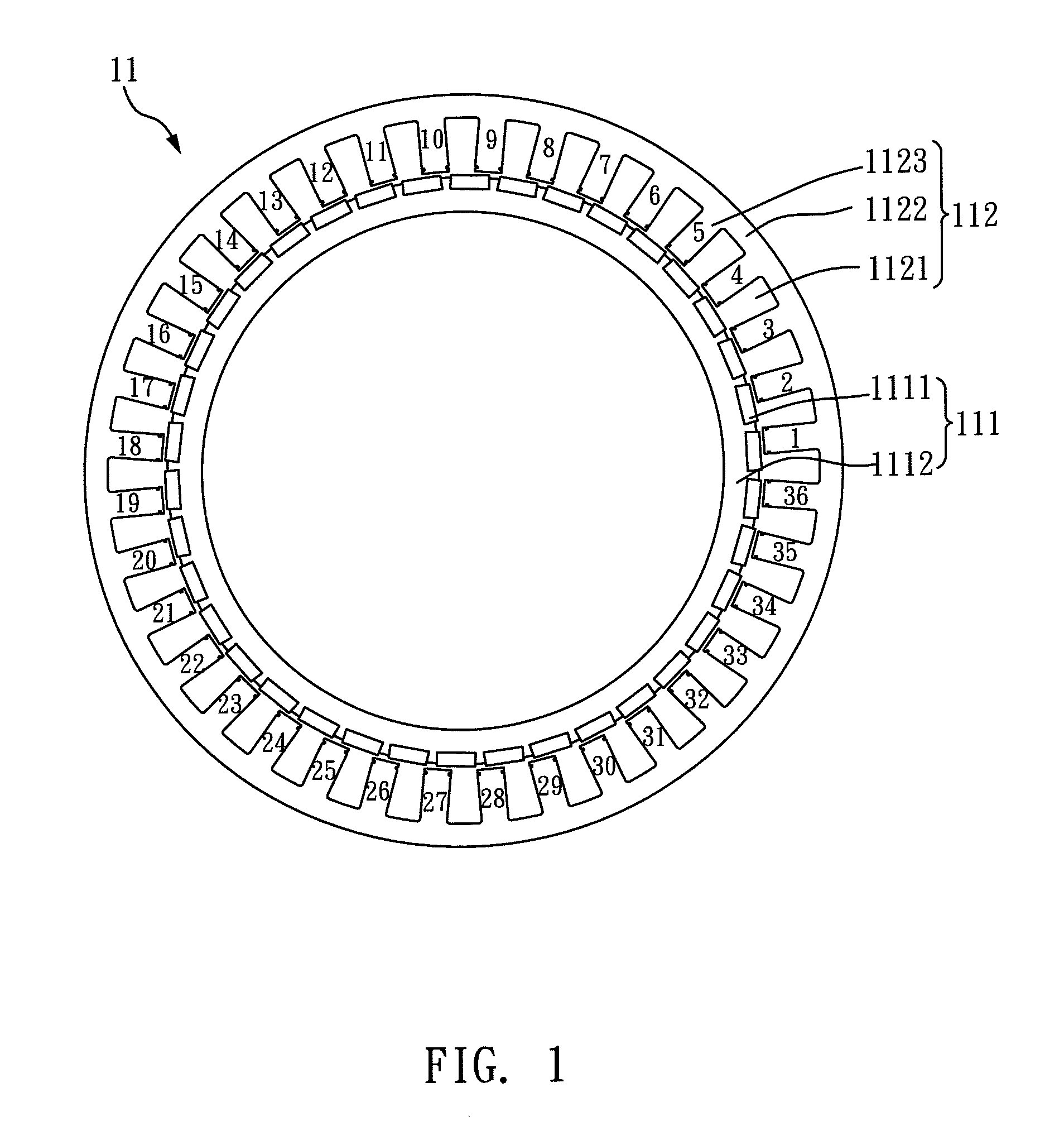
[0031]With reference to FIG. 1, FIG. 1 is a schematic view illustrating the permanent magnet synchronous machine module with a slot / pole combination of 38 poles and 36 slots in accordance with the first embodiment of the present invention. As illustrated in FIG. 1, in the permanent magnet synchronous machine module (11) with 38 poles and 36 slots, there are 38 rotor magnets (1111) disposed on the rotor unit (111) of the module (11). The 38 rotor magnets (1111) are made of permanent magnets, and the material thereof can be NdFeB or ferrite.

[0032]It should be noted that the material of these permanent magnets may include, but is not limited to, NdFeB, ferrite, SmCo, AlNiCo, or the like. The aforementioned 38 rotor magnets (1111) are preferably made of NdFeB. Moreover, the rotor unit (111) has a rotor steel sheet (1112) located at the inner side of the 38 rotor magnets (1111) for increasing the operation efficiency of the per...

embodiment 2

34 Poles 36 Slots Permanent Magnet Synchronous Machine Module

[0047]With reference to FIG. 6, FIG. 6 is a schematic view illustrating the permanent magnet synchronous machine module with a slot / pole combination of 34 poles and 36 slots in accordance with the second embodiment of the present invention. As shown in FIG. 6, in the permanent magnet synchronous machine module (61) with 34 poles and 36 slots in accordance with the second embodiment of the present invention, there are 34 rotor magnets (6111) disposed on the rotor unit (611) of the module (61). The 34 rotor magnets (6111) are made of permanent magnets, and the material thereof can be NdFeB or ferrite.

[0048]It should be noted that the material of these permanent magnets may include, but is not limited to, NdFeB, ferrite, SmCo, AlNiCo or the like. The aforementioned 34 rotor magnets (6111) are preferably made of NdFeB. Moreover, the rotor unit (611) has a rotor steel sheet (6112) located at the inner side of the 34 rotor magne...

embodiment 3

38 Poles 36 Slots Composite Permanent Magnet Synchronous Machine

[0052]With reference to FIG. 7, FIG. 7 is an exploded view illustrating the composite permanent magnet synchronous machine in accordance with the third embodiment of the present invention. As shown in FIG. 7, the composite permanent magnet synchronous machine of the present invention includes: a permanent magnet synchronous machine module (71), a bottom base 72, a top cover (73), and a shaft (74). In addition, the permanent magnet synchronous machine module (71) includes a rotor unit (711) and a stator unit (712), wherein the stator unit (712) surrounds the rotor unit (711) to form an inner-rolling structure as known in the art. Moreover, the bottom base 72 has an accommodation space (721). As shown in FIG. 7, the top cover (73) is assembled with the bottom base 72 to receive the permanent magnet synchronous machine module (71) in between the bottom base 72 and the top cover (73). Furthermore, the top cover (73) has a f...


PUM


Abstract

A composite permanent magnet synchronous machine includes a permanent magnet synchronous machine module having a rotor unit and a stator unit; a bottom base having an accommodation space; a top cover having a front surface; and a shaft penetrating through the front surface. The rotor unit has P rotor magnets and the stator unit has S slots, wherein a tooth part is defined between every two adjacent slots, and a coil is wound on the tooth part, where P is 38N, S is 36N, and N is a positive integer; or P is 34M, S is 36M, and M is a positive integer. The machine is suitable for wind power generators or any other machine structure.

Description

CROSS REFERENCE TO RELATED APPLICATION[0001]This application claims the benefits of the Taiwan Patent Application Serial Number 100133617, filed on Sep. 19, 2011, the subject matter of which is incorporated herein by reference.BACKGROUND OF THE INVENTION[0002]1. Field of the Invention[0003]The present invention relates to a composite permanent magnet synchronous machine and, more particularly, to a composite permanent magnet synchronous machine capable of switching to a different phase, such as three-phase, six-phase, and nine-phase, thus being allowed to connect in parallel with utility power with different voltages of 110 / 220 / 440 V.[0004]2. Description of Related Art[0005]Electrical energy has become essential power for human beings. Currently, thermal power generation is still the most popular way for generating power in the world, and the amount of power generated is also the largest. Typically, thermal power generation is employed to burn fossil fuel, such as coal, petroleum, o...

Claims


Application Information

Patent Timeline
Patent Type & Authority Applications(United States)
IPC IPC(8): H02K11/00H02K21/14
CPCH02K2213/03H02K21/16
Inventor HWANG, JONQ-CHINHSIAO, CHUN-YUYEH, SHENG-NIAN
Owner NAT TAIWAN UNIV OF SCI & TECH
Why Eureka
Try Eureka