
Hydrodynamic axial bearing

a technology of axial bearings and rotating shafts, applied in the direction of bearings, water-acting propulsive elements, shafts, etc., can solve the problems of reducing the load-bearing capacity, rubbing of the comb bearing on the floating disk, and affecting the load-bearing force of the mounting

Inactive Publication Date: 2014-08-28
ABB TURBO SYST
View PDF1 Cites 8 Cited by
  • Summary
  • Abstract
  • Description
  • Claims
  • Application Information

AI Technical Summary

Benefits of technology

The patent text is about a solution to prevent deformation of load-bearing faces in axial mountings caused by temperature gradients, centrifugal, shearing and other forces during operation. This deformation can impair the load-bearing force of the mounting and lead to rubbing of the comb bearing on the floating disk, particularly in the case of a low oil supply pressure. The compensation can be done by using a conical configuration of the axial stop on the bearing housing for a floating disk or a very thin floating disk which is adapted to changing geometric conditions during operation. This compensation can make the axial mounting more robust, reduce rubbing and wear-induced costs and make the turbocharger more operationally reliable.

Problems solved by technology

A deformation of this type of the bearing load-bearing faces can impair the load-bearing force of the mounting.
This deformation can lead to rubbing of the comb bearing on the floating disk, particularly in the case of a low oil supply pressure.
This can reduce the load-bearing capability for geometric reasons and can reduce the centrifugal force-induced pressure build-up in the radial direction, because the outflow resistance for the lubricating oil radially to the outside is reduced.

Method used


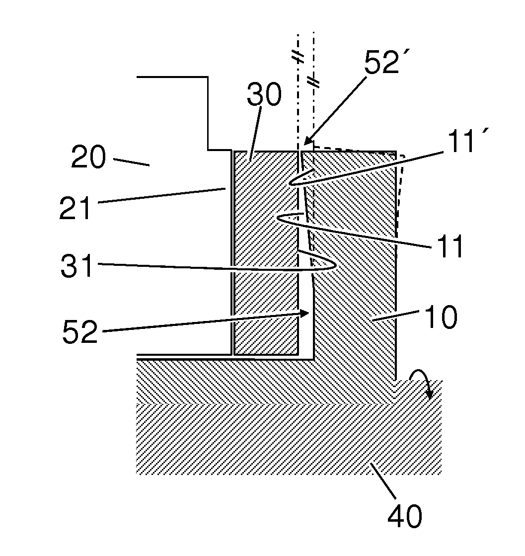
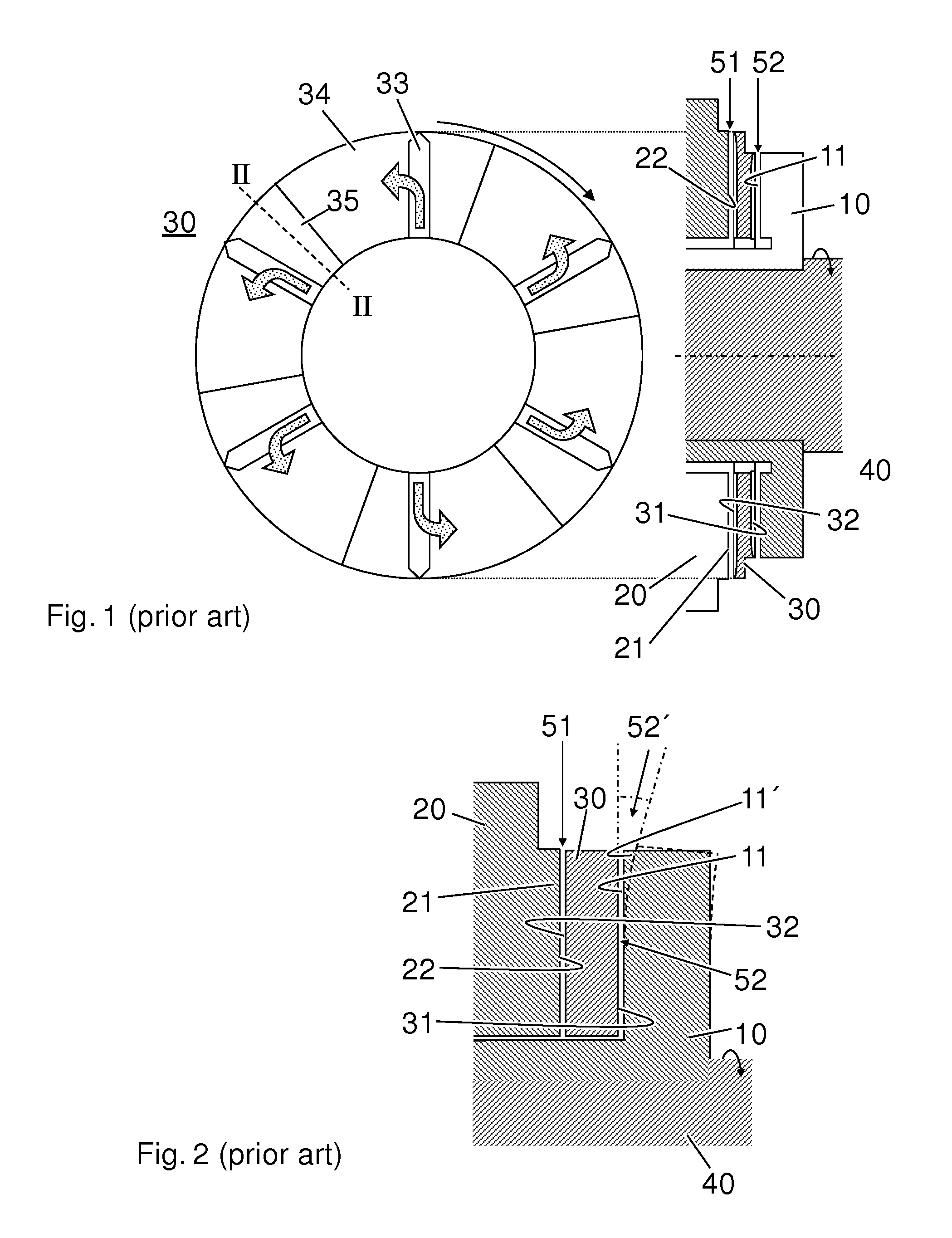
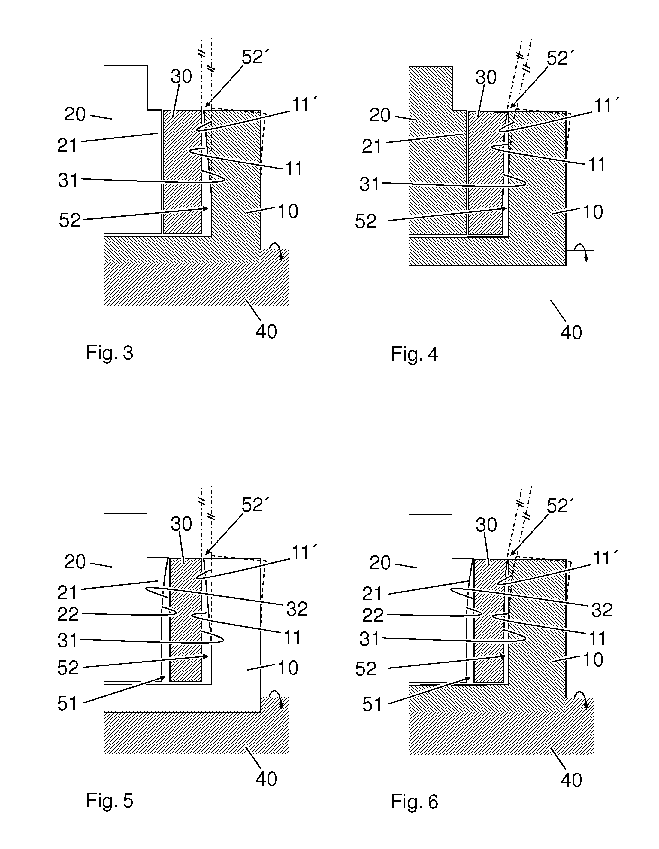
Image

  • Hydrodynamic axial bearing
  • Hydrodynamic axial bearing
  • Hydrodynamic axial bearing

Examples


Embodiment Construction

[0020]Exemplary embodiments of the disclosure can improve the load-bearing capability of a hydrodynamic axial bearing for mounting a shaft which is mounted rotatably in a bearing housing.

[0021]If the gap, which is formed between the load-bearing faces of the axial bearing, is configured so as to be constricted to the outside in the radial direction, by the load-bearing faces being arranged obliquely relative to one another at least in the radially outer region, a reduction in the relative oblique position of the load-bearing faces results during operation on account of the abovementioned deformation of the rotating load-bearing face. The constriction in the radially outer region is reduced, with the result that the load-bearing faces can rest more uniformly on one another during operation.

[0022]If, for example, the bearing comb is manufactured with a conical load-bearing face, that is to say a load-bearing face which is inclined toward the load-bearing face which lies opposite it, t...


PUM


Abstract

A hydrodynamic axial bearing for mounting a shaft which is mounted rotatably in a bearing housing, including an axial stop of the bearing housing and a bearing comb which rotates with the shaft. A lubricating gap, which is loaded with lubricating oil and is delimited by a profiled circular ring face and a sliding face, being formed between the axial stop and the bearing comb. The profiled circular ring face and the sliding face are configured in such a way that the lubricating gap is constricted radially to the outside with regard to the axial direction. As a result, temperature deformations which occur during operation and deformations on account of centrifugal, shearing and other forces in the bearing comb can be compensated for.

Description

RELATED APPLICATIONS[0001]This application claims priority as a continuation application under 35 U.S.C. §120 to PCT / EP2012 / 071729, which was filed as an International Application on Nov. 2, 2012 designating the U.S., and which claims priority to German Application 102011085681.1 filed in Germany on Nov. 3, 2011. The entire contents of these applications are hereby incorporated by reference in their entireties.FIELD[0002]The disclosure relates to the field of hydrodynamic axial mounting of rotating shafts, as are used, for example, in turbomachines, for example in exhaust gas turbochargers.BACKGROUND INFORMATION[0003]If rapidly rotating rotors are loaded with axial shearing forces, load-bearing axial bearings can be used. For example, in the case of turbomachines, such as exhaust gas turbochargers, hydrodynamic axial bearings can be used to absorb axial forces, which can be high as a result of the flow, and to guide the shaft in an axial direction. In order to improve an oblique pos...

Claims


Application Information

Patent Timeline
IPC IPC(8): F01D25/16F01D25/18F04D29/057
CPCF01D25/168F04D29/057F01D25/18F16C17/04F16C33/1075F16C2360/24F05D2240/53F16C17/18
Inventor NEUENSCHWANDER, PETERAMMANN, BRUNODI PIETRO, MARCOSTADELI, MARKUS
Owner ABB TURBO SYST
Learn More