Annular Arrow Fletch

a technology of annull arrow and arrow head, which is applied in the direction of arrows, weapons, projectiles, etc., can solve the problems of time-consuming process, inconvenient traveling and storage of arrows, and inconsistencies in spacing and angles, so as to improve the stability of arrows or other projectiles, eliminate inconsistencies and costs, and facilitate the effect of traveling and storag

Active Publication Date: 2014-08-28
GALL TIMOTHY LEE
View PDF15 Cites 1 Cited by
  • Summary
  • Abstract
  • Description
  • Claims
  • Application Information

AI Technical Summary

Benefits of technology

[0016]In one aspect, the improved stabilization of the arrow or other projectile and resolves prior art issues related to facial pressure interference, fletching inconsistency, environmental sensitivity to; cleaners, glues and adhesives, field replaceability, and erratic arrow flight. An annular arrow fletch consistent with the present invention comprises a unit adapted to slide over the aft end of the shaft of an arrow to a predetermined depth, which is then affixed to the arrow shaft by a nock. The present invention's central elongated cylindrical cylinder cap and an arrow nock are used to maintain the union with an arrow shaft and a point make the arrow components.
[0017]The present invention provides field replaceable annular arrow fletches that eliminates the inconsistencies and costs associated with traditional multi-piece glue adhesive fletching jig systems. The invention also makes traveling and storage of arrows more convenient because the annular arrow fletch can be removed and reinstalled in field as needed.
[0018]The annular arrow fletch consistent with the present invention may easily be mass-produced and is capable of providing high accuracy devices with repetitive results in use. An annular arrow fletch consistent with the present invention may be particularly shaped or otherwise adapted to provide additional aerodynamic features, e.g., increased arrow rotation, improved drag performance, increased arrow stability and or other such flight characteristics.
[0019]Further, the present invention provides an arrow having improved aerodynamic characteristics, resulting in increased flight stability, speed, and accuracy. An arrow consistent with the present invention requires no feathers or traditional fletchings, instead utilizing affixed annular arrow fletch improves aerodynamic when mounted over the aft end of the arrow shaft, and is held in place by the arrow nock. When an annular arrow fletch is affixed to an arrow shaft the center elongated cylindrical cylinder structure of the annular arrow fletch allows for greater clearance between the facial flesh of the archers cheek and the invention. The benefit of the additional clearance reduces and or aids in preventing unwanted contact onto the fletching area of an arrow shaft. The unwanted pressure that is applied onto the arrow shaft fletching area will cause erratic arrow flight effecting speed and accuracy of the shot arrow. Further, since the arrow has less unwanted interfering pressures being applied to the arrow the arrow will be initially released and allowed to travel at a higher acceleration rate due to the clean release. The annular arrow fletch design prevents less impact by crosswind drift and wobble because of less surface area to be impaired by the crosswinds on the fletching. The annular arrow fletch uses a center elongated cylindrical cylinder structure with a cap, an annular wing and fins with micro-groves when affixed to a shaft the fletch will stabilize the flight of an arrow. The annular arrow fletch is made of a distinct center elongated cylindrical cylinder structure and an annular wing shape connected by three fins. The center elongated cylindrical cylinder structure is of larger diameter to except a number of manufactures arrow shafts. The annular arrow fletch center elongated cylindrical cylinder is hollow with smooth walls allowing the arrow shaft to be inserted into the center elongated cylindrical cylinder structure until the shaft engages the central elongated cylindrical cylinder cap at a predetermined depth. The center elongated cylindrical cylinder cap recess is smaller in diameter then an arrow shaft to prevent said arrow shafts from passing through the center elongated cylindrical cylinder. The annular arrow fletch central elongated cylindrical cylinder is in the range of 1.6″ inches in length. The annular arrow fletch center elongated cylindrical cylinder cap has a metal contact incorporated into or on the cap to aid in conductivity contact. The annular arrow fletch central elongated cylindrical cylinder cap recess is open to except industry standard size arrow nocks, which will allow an arrow nock to be inserted into the recess but not pass completely through the opening. When an arrow nock is inserted through the annular arrow fletch central elongated cylindrical cylinder cap and seated into the aft end of an arrow shaft the annular arrow fletch will be affixed to an arrow shaft. When the annular arrow fletch is affixed with a tight fitting arrow nock to an arrow shaft the annular arrow fletch will not move. The annular arrow fletch has three fins that connect the central elongated cylindrical cylinder to the annular wing. The annular arrow fletch fins are equal in size, shape and distances from each other at 120 degrees. The fins bridge the central elongated cylindrical cylinder to the outer annular wing. The bridging begins at the base of the annular arrow fletch and continues to the full height of the annular wing. The fins are at perpendicular angle disposed substantially orthogonally at the base and zero helical off set. The annular arrow fletch fins have a rounded edges at the base; the fins will have micro-grooves on the topside of each of the 3 fins. The annular arrow fletch fin micro-grooves begin at the base of the fin and continues equaling the height of the annular wing. The annular arrow fletch fin micro-groves run parallel to the central elongated cylindrical cylinder structure. The annular arrow fletch fins and the annular wing will be thicker at the base and taper and become thinner as the heights increases, mimicking an airfoil design. The annular arrow fletch fin micro-groves will direct air over the micro-groves causing the arrow to rotate on the arrow shaft axis when launched from a bow. The annular arrow fletch outer annular wing is in the range of 1.02″ inches in diameter and one half (0.5″) inches tall.

Problems solved by technology

This process is time consuming and introduces inconsistencies in spacing and angles.
Moreover, polluting and toxic chemicals are often required to clean the arrow shaft prior to gluing.
Further, conventionally fletched arrows are easily damaged in the field or while in storage.
When damaged, conventional fletching is normally not considered field replaceable and can be difficult to repair.
The unwanted pressure applied to the arrow by the archer's facial cheek or facemask would have an adverse effect on the arrow upon release causing erratic inconsistent arrow flight.
(7) Finally, prior art stabilizing methods require the fletching to pass over and / or through the arrow rest causing possible interference with the rest, thus imposing certain design limitations.
Fixed arrow rests may interfere with the flight of an arrow through inadvertent contact, thereby adversely effecting flight performance, as well as damaging the fletching through such contact.
While fall-away or offset rests most often are used to reduce the incidence of contact between the arrow rest and the fletching of an arrow, such rests can be expensive and do not resolve other above-mentioned problems associated with fletching, fletching repair and or replacement tools, jigs, required skills and the use of toxic cleaners, glues and adhesives.

Method used


Image

  • Annular Arrow Fletch
  • Annular Arrow Fletch

Examples


Embodiment Construction

[0028]Although the present embodiments have been described with reference to specific example embodiments, it will be evident that various modifications and changes may be made to these embodiments without departing from the broader spirit and scope of the various embodiments.

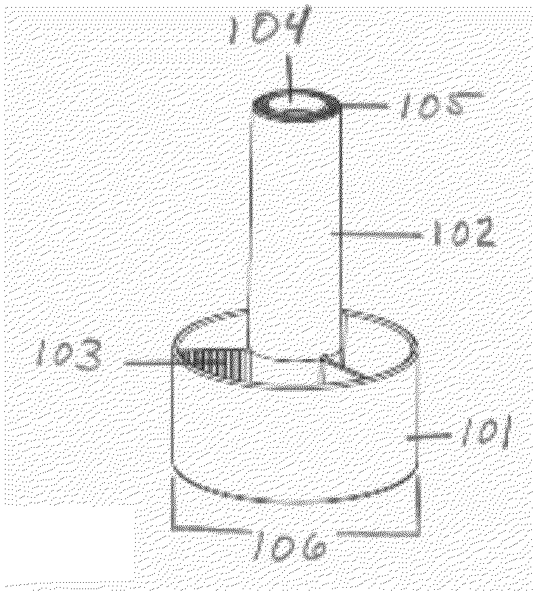
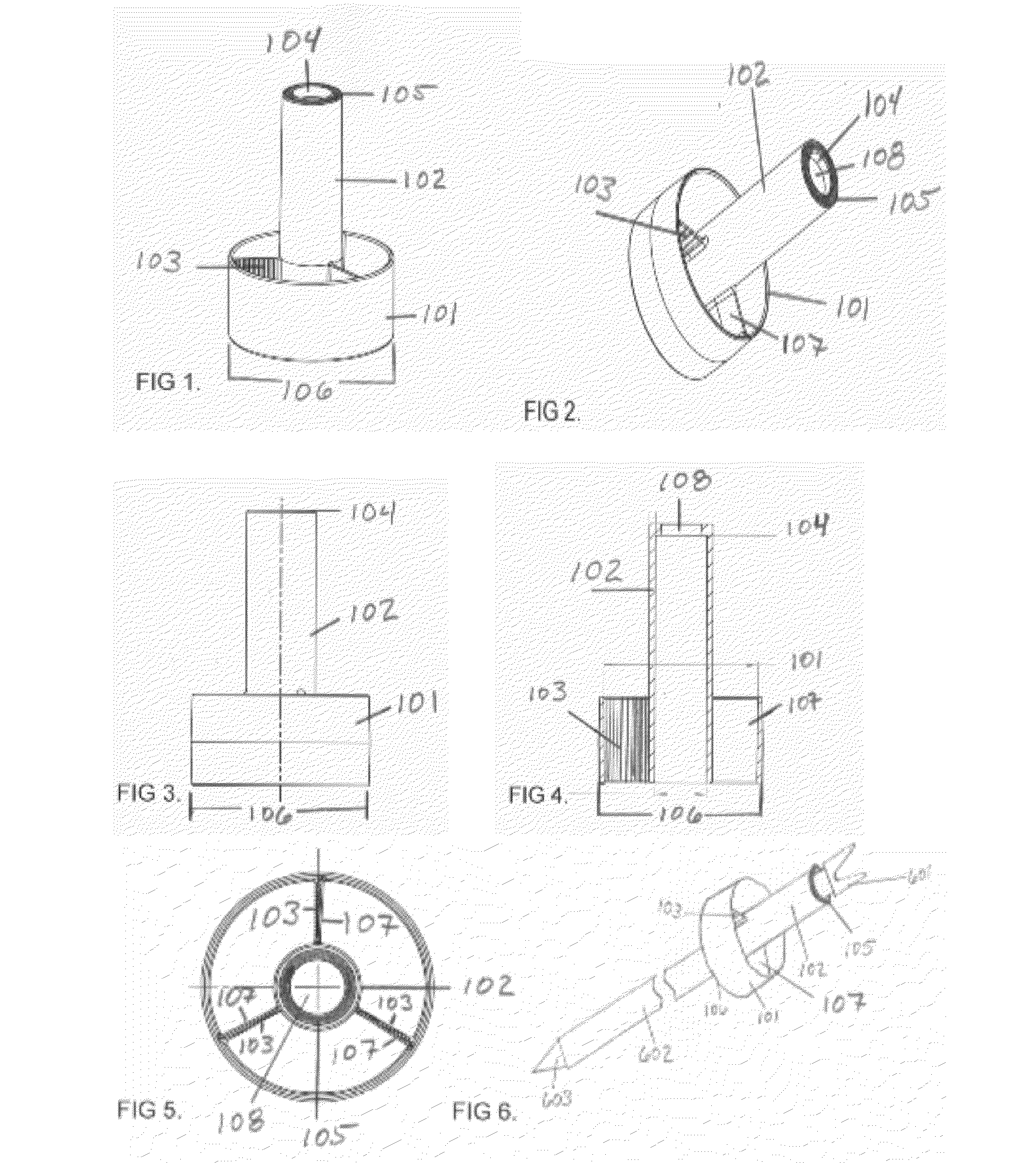
[0029]A conventional arrow comprises a tip, a shaft, and a prior art stabilization system comprising a plurality of glued fins as feathers, veins and or fletching's. The fins are fixed to the shaft and are easily damaged or lost through contact with other surfaces, e.g., with the bow used to launch the arrow or with butt material (backing, bales, man made targets or dirt designed to stop and hold arrows) of a paper target, or with a game animal when hunting. The aft end of the arrow may comprise a recess (not shown) formed therein for engagement (e.g., via a interference fit) with an arrow nock that secures the arrow in place on a bowstring before launch, e.g., by disposing an arrow nocked to a bowstring (not s...


PUM


Abstract

The invention is an annular arrow fletch arrow stabilizer are therefor provided. The annular arrow fletch is used for; stabilizing arrow flight, providing better clearance and functionality then conventional fixed glued tail feathers, the invention can be used with light emitting diode arrow nocks. The invention improves current arrow shaft stabilization technology with reduced assembly labor cost, the elimination of facial and or face mask interference issues providing more clearance, improved accuracy, repeatable production with the consistent injection mold production of the annular arrow fletch, easy replacement of the annular arrow fletch in the field, and improved arrow storage. The annular arrow fletch incorporates a metallic contact point, which will work with all light emitting nocks. The design of the annular arrow fletch is so that it is affixed to an arrow by an arrow nock and comprises of an annular wing, a central elongated cylindrical cylinder with a cap and a plurality of fins with micro-groves and a metal contact. In use, the annular arrow fletch is affixed at the aft end of the arrow by an arrow nock prior to launch.

Description

CROSS REFERENCE TO RELATED APPLICATION[0001]The listed prior application claims the benefit of U.S. Design patent application 29 / 421,121, filed: May 25, 2012, the teachings of which are incorporated herein by reference.Design application: 29 / 421,121Inventor: Timothy Gall, Pro-SeFiled: May 25, 2012FIELD OF THE INVENTION[0002]This invention relates generally to a fletching of an arrow in the field of archery. The annular arrow fletch is to replace the use of natural or man made, synthetic vanes, feathers or fletchings on an arrow shaft.DEFINITIONS[0003]“Fletching” is a generic term used to describe the fins of an arrow that guide and stabilize the arrow during flight. These fins, when made from natural feathers, are commonly referred to collectively as “fletching”, comprising individual “fletches.” When made from plastic or other man-made materials, these fins are called “vanes.” In the present application, the terms “fletching,”“feathers,”“vanes,” and “fins” are employed throughout w...

Claims


Application Information

Patent Timeline
Patent Type & Authority Applications(United States)
IPC IPC(8): F42B6/06
CPCF42B6/06F42B10/36
Inventor GALL, TIMOTHY LEE
Owner GALL TIMOTHY LEE
Why Eureka
Try Eureka