
Bicycle gearshift with improved precision control

a technology of precision control and bicycle gear shift, which is applied in the direction of gear control, belt/chain/gearing, mechanical equipment, etc., can solve the problem that the lifting of the chain guide towards the sprocket does not have a limitation dictated by the technology

Active Publication Date: 2014-08-28
CAMPAGNOLO SRL
View PDF16 Cites 38 Cited by
  • Summary
  • Abstract
  • Description
  • Claims
  • Application Information

AI Technical Summary

Benefits of technology

The invention provides a solution for improving the precision of gearshift control, especially in lower gears, by making the system more sensitive to changes in the position of the chain guide. This is achieved by moving closer to the smaller sprockets. Additionally, the use of mechanical actuation provides faster response times to the actuation command compared to direct actuation, which provides further benefits.

Problems solved by technology

The lifting of the chain guide towards the sprockets does, however, have a limitation dictated by the sprocket of largest diameter.
Moreover, getting too close to the sprocket with largest diameter is the cause of drawbacks such as the feeling of sudden gearshifting between the lowest gears to the next one, as well as slipping between the chain and the chain guide in the case of the lowest gear and pedalling backwards.

Method used


Image

  • Bicycle gearshift with improved precision control
  • Bicycle gearshift with improved precision control
  • Bicycle gearshift with improved precision control

Examples


third embodiment

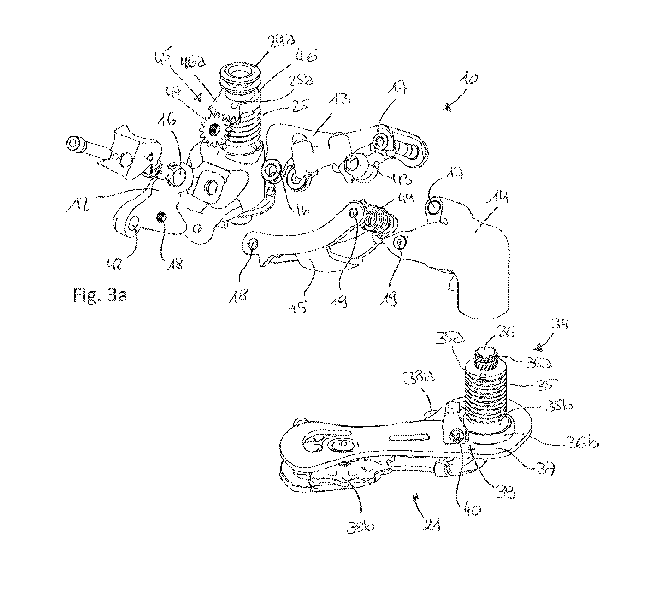
[0099]The preferred embodiment of FIGS. 5a-5b foresees the use of an electric motor 30 with rotary outlet shaft (not illustrated). In such a third embodiment, the motor 30 is arranged inside the four-bar linkage-kinematic mechanism 11 so as to have its rotary outlet axis (not shown) arranged perpendicular to the shaft 29 arranged between diagonally opposite pin elements.

[0100]A reduction stage (not illustrated) is also provided for, suitable for transferring the rotary motion of the outlet shaft of the motor 30 to an actuation pin 50 substantially arranged between the first 16 and the third 18 pin element and parallel to them.

[0101]The actuation pin 50 is free to rotate with respect to the first connecting rod 13 and to the base body 12 and carries a toothed spindle 49 that rotates as a unit with it 50 suitable for cooperating, by shape coupling, with a rack 51 formed on the shaft 29 in order to determine a displacement in translation thereof.

[0102]The shape coupling between the too...

fourth embodiment

[0131]According to this fourth embodiment therefore, the variation of the preload of the second chain tensioning spring 35 is correlated to an axial displacement of the chain guide 21.

[0132]The operation of the bicycle gearshift 10 according to the invention is as follows.

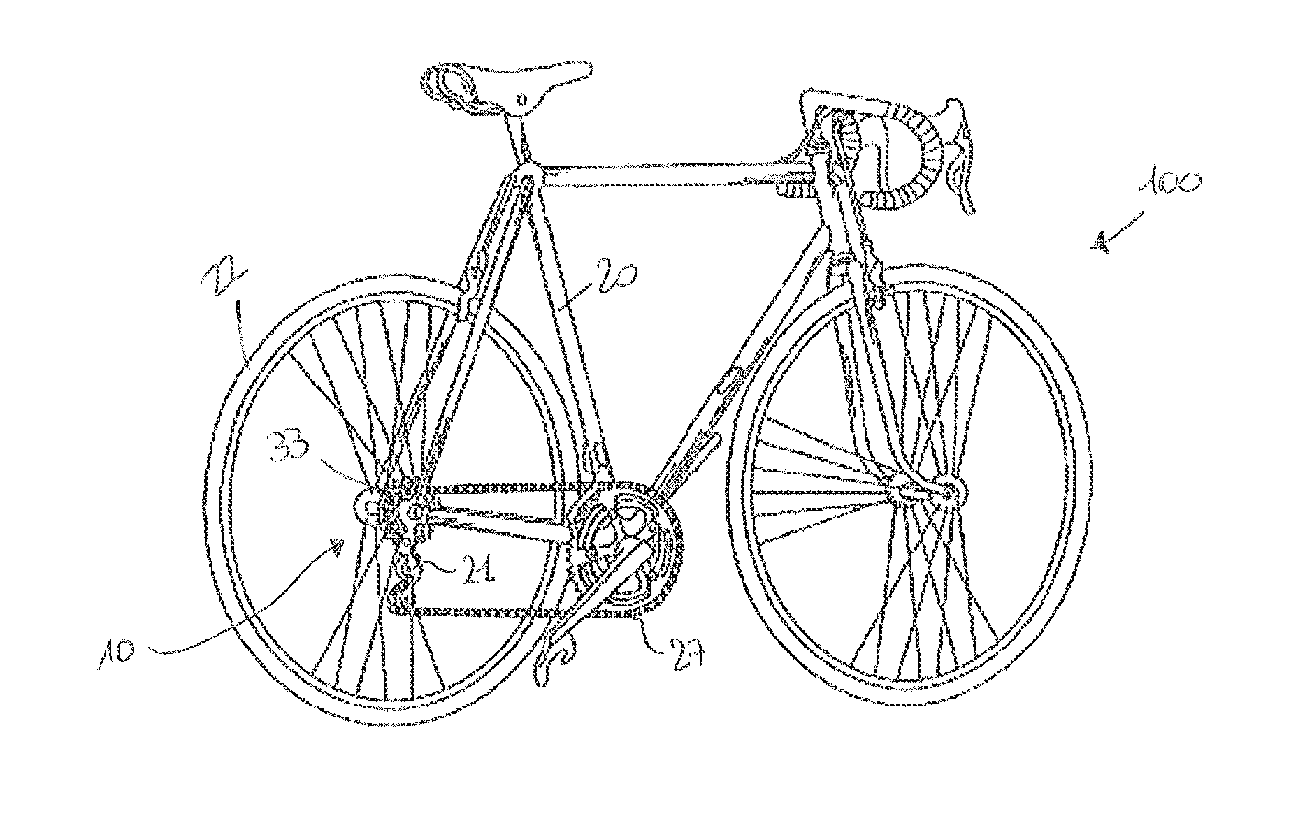
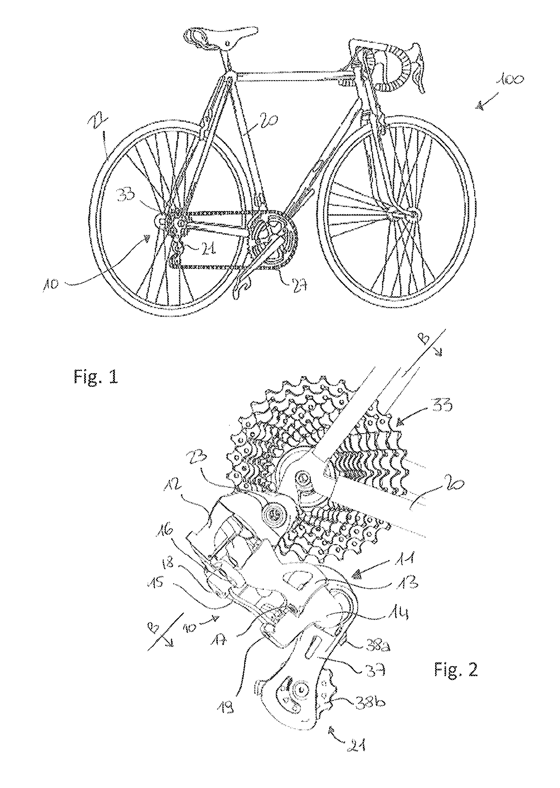
[0133]Following actuation of the gearshift 10, the chain guide 21 is moved along a direction having at least one axial component, i.e. a component parallel to the axis A of the sprockets 33, to go up to the sprocket 33 on which the transmission chain 27 must be positioned.

[0134]FIGS. 7a-7b and 8a-8b respectively show a gearshift of the state of the art and a gearshift according to the present invention in the first and last position, i.e. at the smallest sprocket 33 and at the largest one.

[0135]Such a displacement is determined by a deformation of the four-bar linkage-kinematic mechanism 11 controlled through the mechanical or motorised actuation means 28 according to the particular embodiment.

[0136]After the actua...


PUM


Abstract

The present invention refers to a bicycle gearshift with improved precision control, which comprises a kinematic mechanism in the form of a four-bar linkage with a base body and a mobile body connected together through a pair of connecting rods articulated to the base body and to the mobile body at four pin elements, each pair of opposite pin elements of the four pin elements defining a diagonal of the four-bar linkage-kinematic mechanism, the base body comprising a first attachment group to a bicycle frame and the mobile body being connected to a chain guide at a second attachment group, the four-bar linkage-kinematic mechanism being associated with gearshift actuation means suitable for deforming the four-bar linkage-kinematic mechanism so as to determine a displacement of the mobile body with respect to said base body and consequently a primary displacement of the chain guide in the axial direction with respect to the axis (A) of a cogset, at least one from the first attachment group and the second attachment group comprising a chain tensioning spring, the chain tensioning spring determining a set-up of the chain guide when engaged with a chain of a bicycle transmission, and it is characterised in that it comprises a kinematic mechanism for adjusting the preload of the chain tensioning spring as a function of the primary displacement of the chain guide so as to determine a variation in the set-up of the chain guide.

Description

CROSS REFERENCE TO RELATED APPLICATION[0001]This application claims the benefit of Italian Application No. MI2013A000252, which was filed on Feb. 22, 2013, and is incorporated herein by reference as if fully set forth.FIELD OF INVENTION[0002]The present invention refers to a bicycle gearshift with improved precision control.BACKGROUND[0003]By bicycle gearshift a mechanical device is meant, that causes the transmission chain to move between different toothed wheels, for this purpose moving a chain guide in which the chain is engaged.[0004]In the context of this patent description and of the following claims, the gearshift being referred to is the rear one that moves the transmission chain between the different sprockets of a cogset associated with the rear wheel of the bicycle.[0005]Normally, the bicycle gearshift comprises a kinematic mechanism in the form of a four-bar linkage (typically an articulated parallelogram) with a base body and a mobile body opposite the base body in the ...

Claims


Application Information

Patent Timeline
Patent Type & Authority Applications(United States)
IPC IPC(8): B62M9/126
CPCB62M9/126B62M9/122B62M9/1242B62M9/1248
Inventor PASQUA, PAOLOLAZZARIN, LEOPOLDO
Owner CAMPAGNOLO SRL
Learn More