Surgical technique and apparatus for proximal humeral fracture repair

a humeral fracture and humeral nail technology, applied in the field of humeral nail, can solve the problems of not being entirely suitable for treatment of more complex fractures, not providing a mechanism to reduce fractures and retain fragments, and not providing a mechanism to adjust the location of fragments

Active Publication Date: 2014-08-28
TORNIER SA SAINT ISMIER
View PDF75 Cites 8 Cited by
  • Summary
  • Abstract
  • Description
  • Claims
  • Application Information

AI Technical Summary

Benefits of technology

[0008]The present invention relates to a system and method for repairing a proximal humeral fracture using a humeral nail for both reduction and retention of the fragments to the correct anatomical position. The system and method provides for limited rotation of the humeral nail within the medullary canal to adjust the position of a bone fragment relative to the humeral head.
[0009]In the preferred embodiment, the procedure is performed entirely percutaneously without the use of a reduction device. Small incisions are made in the skin at selected locations, rather than requiring the entire shoulder joint to be exposed. The humeral nail can be inserted percutaneously, with minimal risk of damage to the rotator cuff. The positioning of the proximal screws limits interference with the articular surface of the humeral head. In the preferred embodiment, no screws are required to retain the humeral head in its anatomical position. Rather, the humeral head is retained medially by the glenoid, anteriorly and posteriorly by the rotator cuff muscles and the tuberosities and superiorly by rotator cuff muscle.
[0011]The humeral nail is positioned in the medullary canal in the humerus. The humeral nail is preferably substantially straight which permits it to rotate after insertion in the medullary canal and helps avoid the need to insert the nail through the insertion of the cuff. A first proximal screw is used to move one of the greater or lesser tuberosities fragmented from the humerus toward the humeral nail. The distal tip of the first proximal screw is preferably not advanced substantially beyond the humeral nail. Consequently, the fragment of the greater or lesser tuberosity attached to the humeral nail and the humeral nail itself can be rotated without damaging surrounding bony structures and soft tissues. After the initial movement of the fragment of the greater or lesser tuberosity by the first proximal screw, the attached fragment of the greater or lesser tuberosity is reduced by rotation with the humeral nail to an anatomically optimum position.
[0015]The present invention is also directed to a method of reattaching a bone fragment to the proximal humerus. The method includes attaching an aiming device to a proximal end of a substantially straight humeral nail. A distal end of the humeral nail is introduced into a medullary canal of the humerus. An aiming device is used to locate a first proximal screw through the bone fragment, into the proximal humerus, and into a first proximal bore in the proximal end of the humeral nail. The first proximal screw is advanced into the first proximal bore to stabilize the bone fragment relative to the humeral nail and, in some embodiments, to bring the bone fragment into engagement with the proximal humerus. The distal end of the first proximal screw preferably does not substantially extend past the humeral nail. The humeral nail is then rotated within the medullary canal of the humerus so that the bone fragment is reduced to an anatomically optimal location. A second proximal screw is engaged with the proximal humerus and a second proximal bore in the proximal end of the humeral nail to prevent further rotation of the humeral nail.

Problems solved by technology

These methods, however, are not entirely suitable for treatment of more complex fractures, or when tissues are weakened by disease.
Huebner does not, however, provide a mechanism to reduce the fracture and retain the fragments during fixation.
Also, if a screw is not accurately located in the fragment, Huebner does not provide a mechanism to adjust the location of the fragment relative to the humeral head.

Method used


Image

  • Surgical technique and apparatus for proximal humeral fracture repair
  • Surgical technique and apparatus for proximal humeral fracture repair
  • Surgical technique and apparatus for proximal humeral fracture repair

Examples


Embodiment Construction

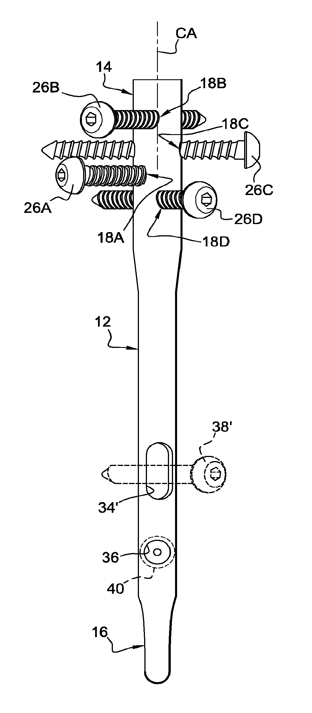
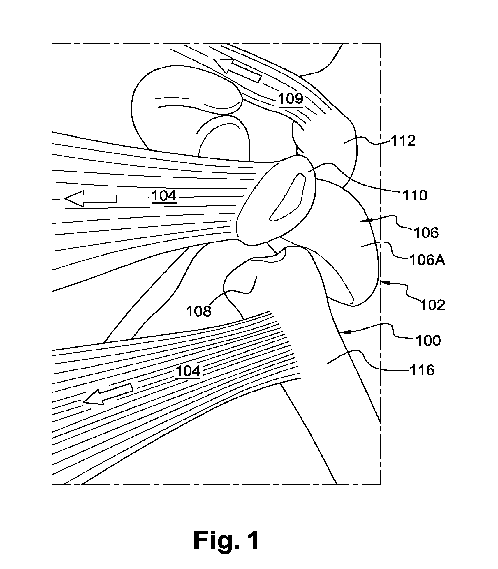
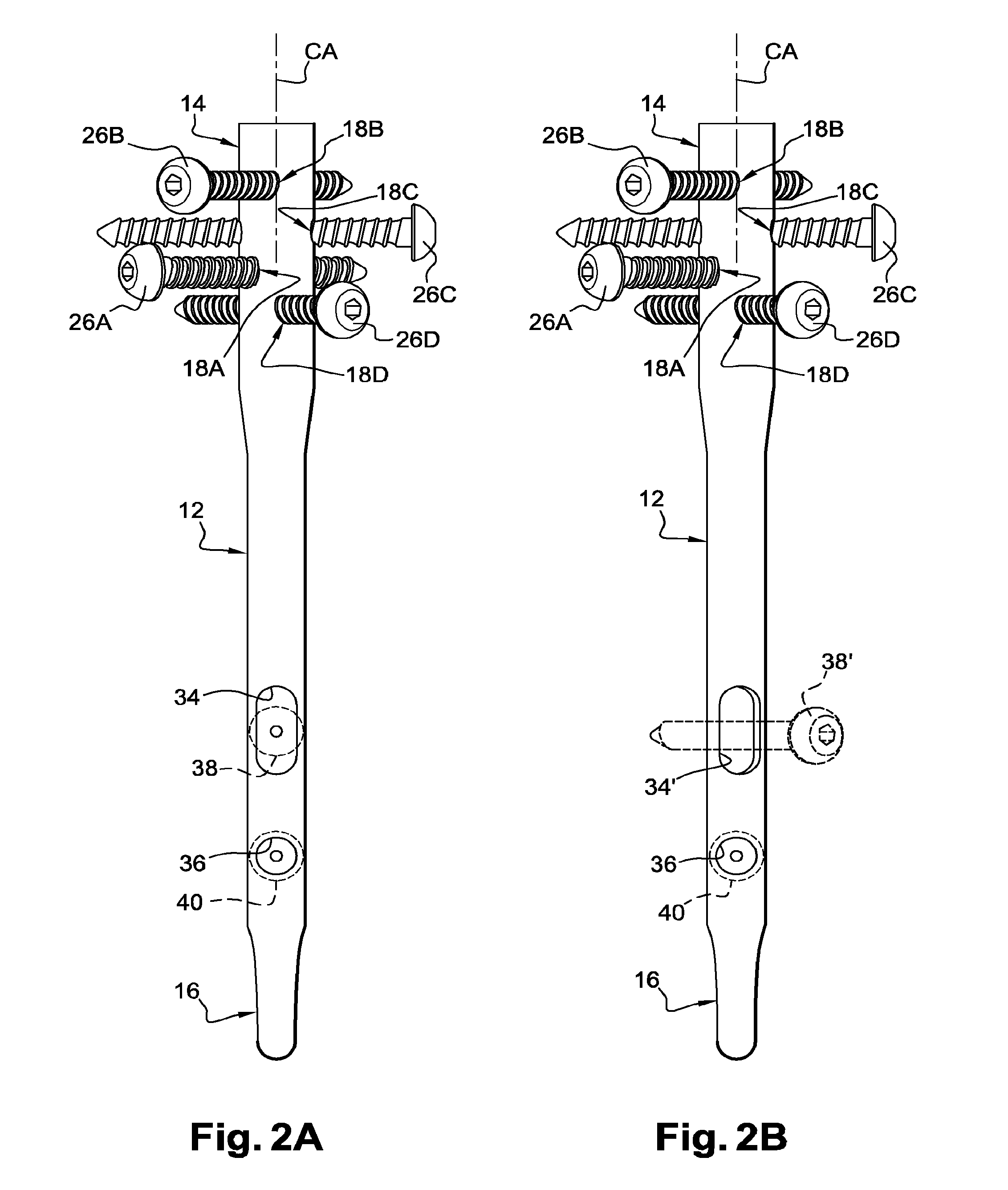
[0032]FIGS. 2A, 2B, 3, 4A-E and 5 show a schematic view of a humeral nail 10. As shown in FIG. 3, this humeral nail is intended to be implanted in the humerus 100, shown in FIG. 1 already described, of a patient to fixate a fracture F at or proximate the greater tuberosity 110 and lesser tuberosity 112 of the proximal humerus. The humeral nail 10 includes a substantially linear shaft 12 having a proximal portion 14 and a distal portion 16. The humeral nail 10 is introduced through the humeral head 106 of the humerus 100 and extends within the humeral shaft 116 such that the distal end 16 of the humeral nail 10 is positioned within the medullary canal of the humeral shaft 116.

[0033]It will be noted that the shown humeral nail 10 is designed to be implanted in the right humerus of a patient. A humeral nail that is to be implanted in the left humerus of a patient will be a mirror-image of the humeral nail depicted in the figures.

[0034]In the preferred embodiment, small incisions are ma...


PUM


Abstract

A method and apparatus of reattaching a bone fragment to a proximal humerus of a humerus in a shoulder joint. The method includes introducing a distal end of the humeral nail into a medullary canal of the humerus. A first proximal screw is engaged with the bone fragment and a first proximal bore in the proximal end of the humeral nail to move the bone fragment toward the proximal humerus. The humeral nail and the attached bone fragment are rotated relative to the medullary canal of the humerus to position the bone fragment to an anatomically optimal location. The bone fragment is preferably one of a greater or lesser tuberosity of the proximal humerus. The method and apparatus can be used to reattach bone fragments in a variety of other joints.

Description

CROSS REFERENCE TO RELATED APPLICATIONS[0001]This application is a divisional of U.S. application Ser. No. 12 / 990,772, filed Nov. 2, 2010, which is a national phase application of PCT / IB2009 / 053468, filed pursuant to 35 U.S.C. §371, which claims priority to U.S. provisional patent application 61 / 051,320, filed May 7, 2008, both of which are herein incorporated by reference in their entireties.FIELD OF THE INVENTION[0002]The present invention relates to a method and apparatus for fixation of proximal humeral fractures. In particular, the present invention relates to a humeral nail for reduction and orientation of the tuberosities at a humeral fracture site.BACKGROUND OF THE INVENTION[0003]As illustrated in FIG. 1, the humerus 100 of the upper arm is part of a “ball and socket” joint at the shoulder 102. The proximal humerus 102 includes a large rounded humeral head 106 joined to the humerus shaft 116 by a humeral neck 108 and two eminences, the greater and lesser tuberosities 110, 11...

Claims


Application Information

Patent Timeline
Patent Type & Authority Applications(United States)
IPC IPC(8): A61B17/72
CPCA61B17/7241A61B17/72A61B17/7233
Inventor BOILEAU, PASCALBAROUCH, LOICHATZIDAKIS, ARMODIOSFEHRINGER, EDWARDBERGER, JEAN-MARIEHODOREK, BRIAN C.
Owner TORNIER SA SAINT ISMIER
Why Eureka
Try Eureka