Automatic faucets

a faucet and automatic technology, applied in the direction of functional valve types, machines/engines, operating means/releasing devices of valves, etc., can solve the problems of adversely affecting the hydraulic control, difficult to accurately control the on-time of the faucet, and individual hand washing time, so as to prevent wrong polarity installation, precise metering, and reduce power consumption

Active Publication Date: 2014-09-04
SLOAN VALVE COMPANY
View PDF13 Cites 21 Cited by
  • Summary
  • Abstract
  • Description
  • Claims
  • Application Information

AI Technical Summary

Benefits of technology

[0019]The control module (control system unit) may include the valve module including the electromechanical actuator (a solenoid actuator) and an optional filter. The actuator housing is constructed to enables an auto shut-off by turning the actuator housing (i.e., turn shut-off) and thus there is no need to shut the water off in case of maintenance, valve changing, or filter cleaning. The combination of filter attached to removable valve module (i.e., valve cartridge) and the turn shut-off associated with the electromagnetic actuator allows for inspecting and cleaning of the filter without tools and without having to shutoff the water supply.
[0030]According to yet another aspect, the faucet may be self-contained battery operated, electronic faucet which can operate for over two, three or more years between battery replacements. The faucet which has a minimum number of moving parts, and the individual parts may be accessed quite easily for maintenance purposes. The faucets can be manufactured and maintained at relatively low cost.

Problems solved by technology

If the water temperature in an automatic faucet is not in an optimal range, individuals tend to shorten their hand washing time.
The hydraulically timed faucets are disadvantaged in that it is difficult to accurately control the on-time of the faucet over the long term because of mains pressure changes and foreign matter build up in the faucet which can adversely affect the hydraulic controls within the faucet.
Furthermore, some faucets can not always discriminate between a users hand and other substances and objects which may be brought into proximity to the faucet, e.g., a reflective object disposed opposite the faucet's infrared transceiver, soap build up on the faucet's proximity sensor, etc.
Resultantly, those prior faucets may be turned on inadvertently and / or remain on for too long a time resulting in wastage of water

Method used


Image

  • Automatic faucets
  • Automatic faucets
  • Automatic faucets

Examples


Embodiment Construction

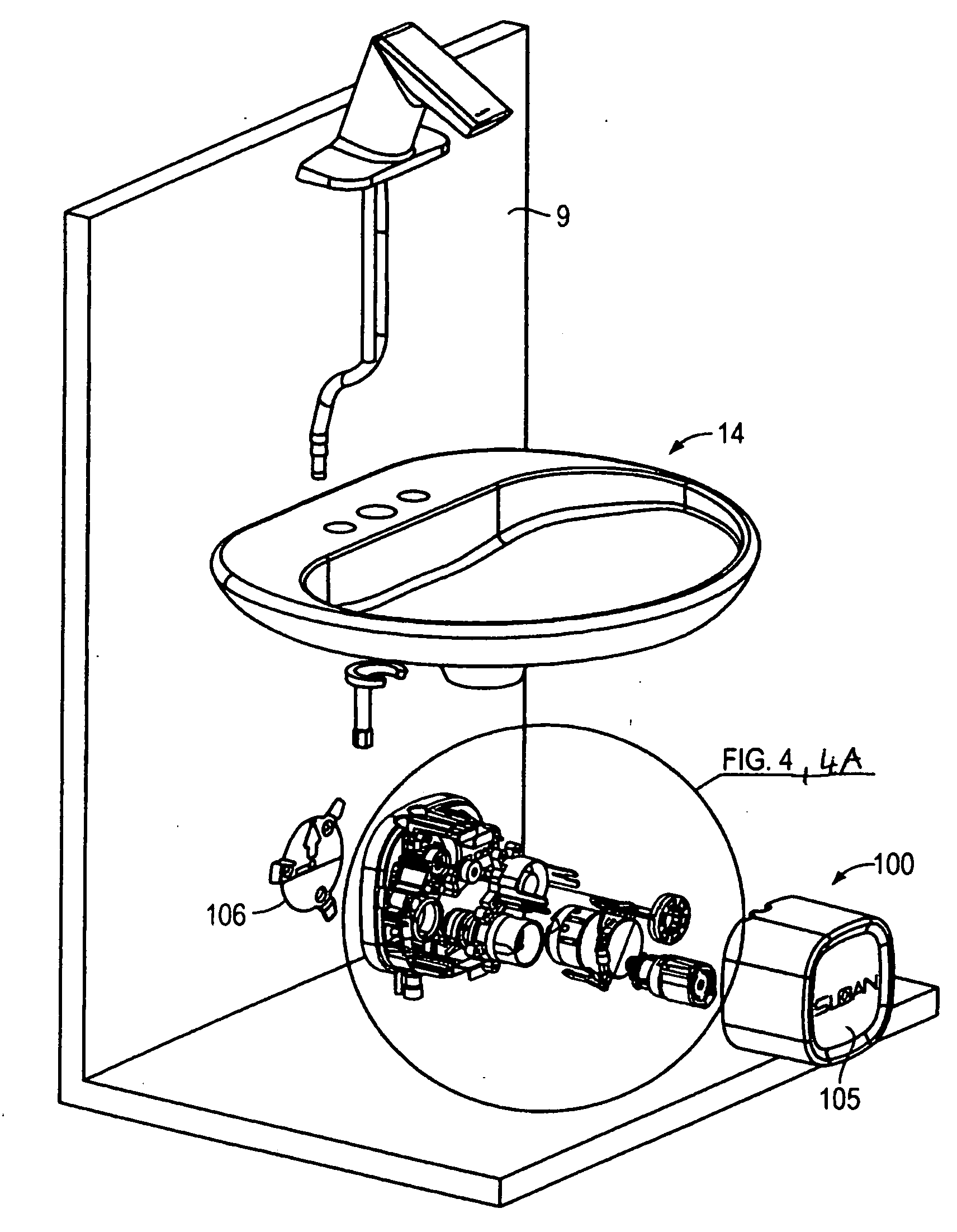
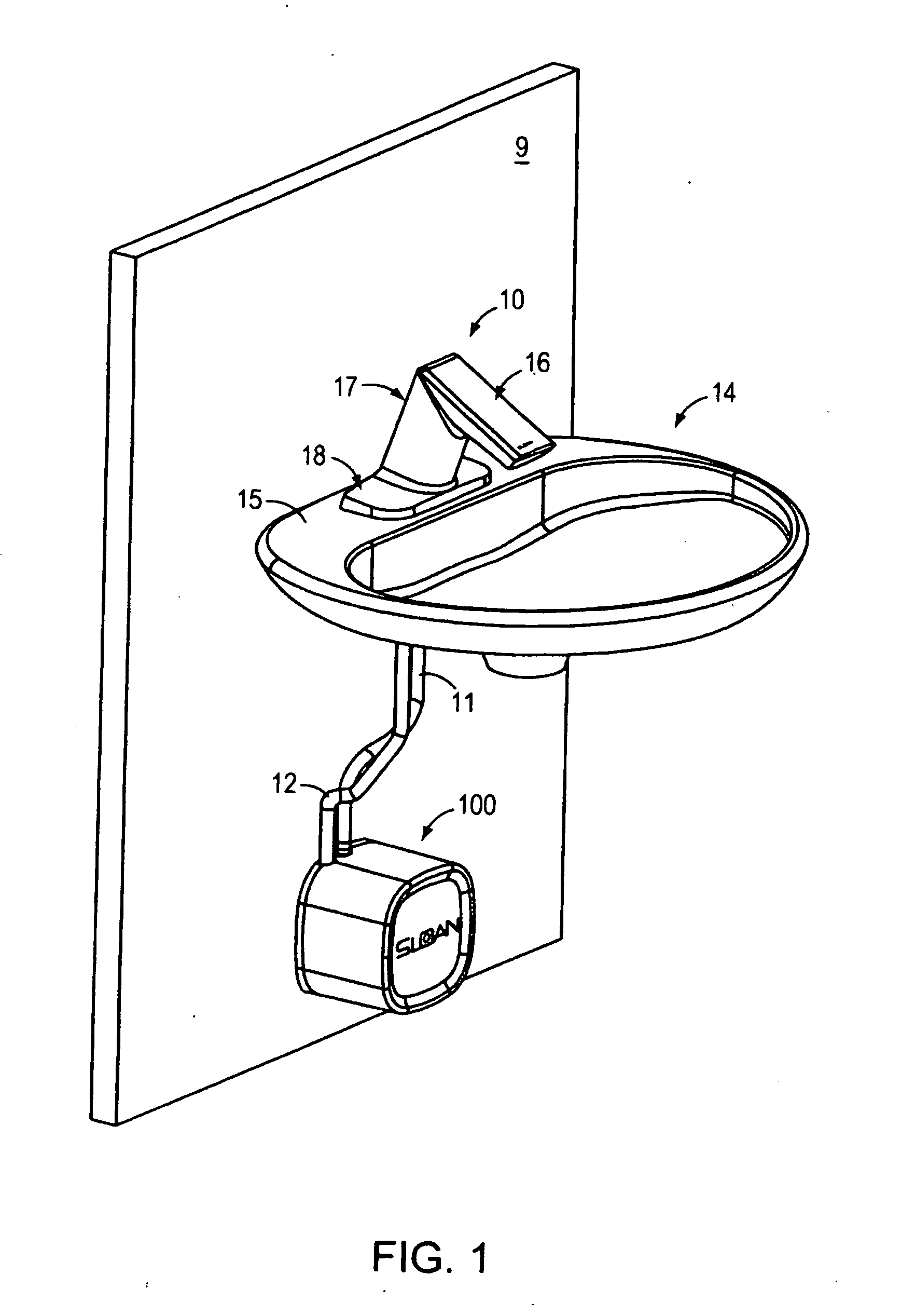
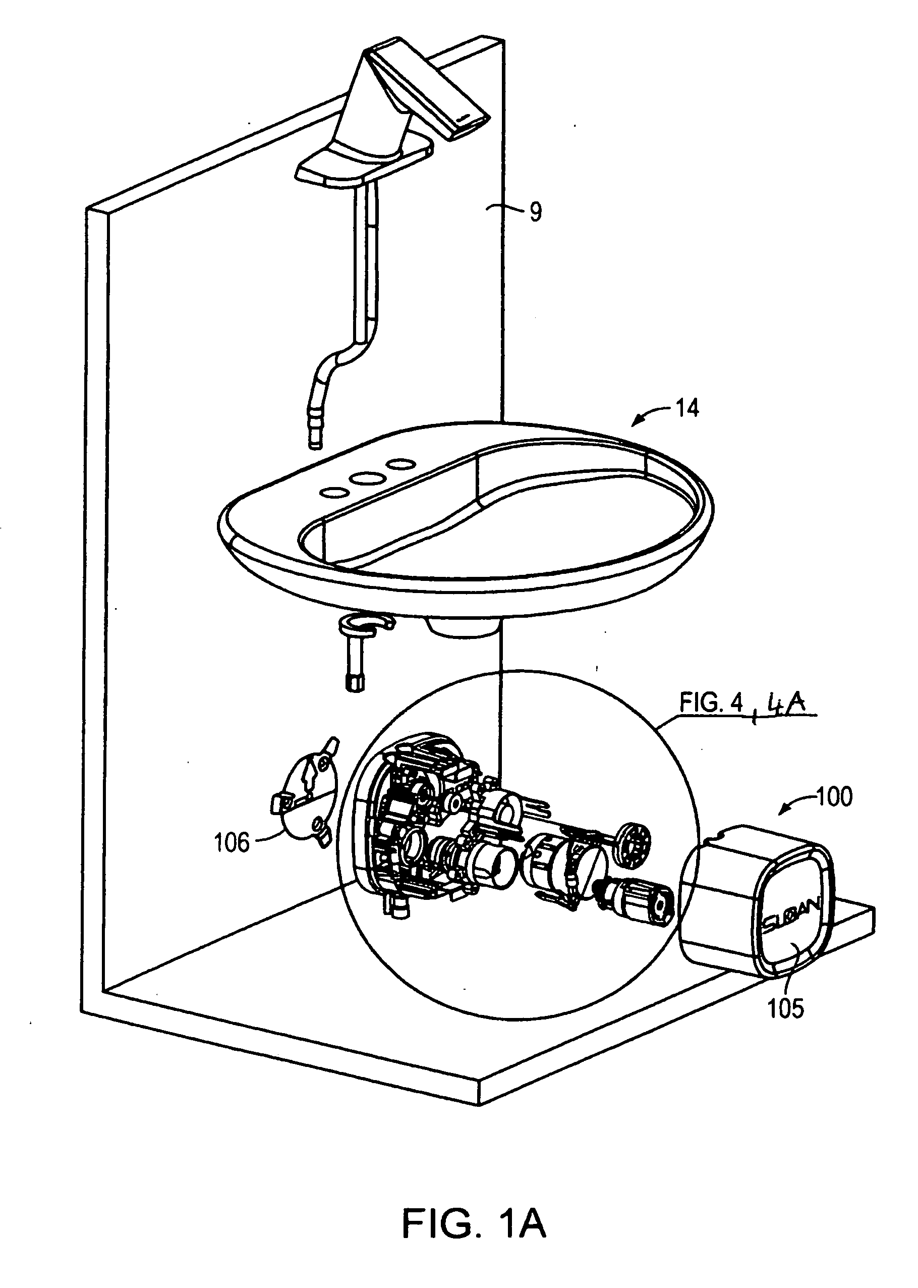
[0069]Referring to FIG. 1, a water faucet 10 is shown mounted to a sink 14, wherein a faucet base 18 is in contact with a top sink surface 15. The faucet includes a housing or encasement body 17 and a faucet crown 16. Faucet 10 is electrically coupled to a control manifold (control system unit) 100 using electrical line 11 and receives water via a water line 12. FIG. 1A illustrates faucet 10 with control system unit 100 shown in an exploded view. Water line 12 is coupled to control center unit 100 using a quick connect arrangement (shown in FIG. 4E) and provides mixed hot / cold water. That is, there is a hot cold mixing unit (not shown in FIGS. 1 and 1A) located below sink 14. Control system unit 100 includes a plastic manifold 12, i.e., a base designed to accept the individual modules, and a cover 105.

[0070]FIGS. 2 and 2A show two different mounting embodiments of faucet 10, shown in FIG. 1, to sink 14. These mounting embodiments are also applicable to faucet 10A, shown in FIG. 9. T...


PUM


Abstract

An automatic faucet includes a housing forming partially an internal barrel and a faucet head and being constructed to include at least one water inlet conduit extending into said barrel and a water outlet for delivering water from a spout. The automatic faucet also includes a faucet head having a removable faucet crown and the spout, wherein the faucet crown is removably mounted to the faucet head. The automatic faucet also includes a valve module, a sensor module, a battery module, a turbine module, and a control module. The valve module includes a valve controlled by an electromagnetic actuator for controlling the water flow from the spout. The sensor module is constructed to provide sensor data influenced by a user. The control module is constructed to control opening and closing of the valve by providing signals to the electromagnetic actuator. The control module is also constructed to receive sensor data from the sensor module and execute a sensing algorithm. The control module is also constructed to execute a power management algorithm for managing electrical power generated by the water turbine and provided to and from the battery.

Description

[0001]This application is a continuation of PCT Appl. PCT / US2012 / 000337, filed on Jul. 31, 2012, which is a continuation-in-part of PCT Application PCT / US2012 / 000150, filed on Mar. 15, 2012, entitled “Automatic Faucets,” which claims priority to U.S. Provisional Application 61 / 574,345, filed on Jul. 31, 2011, and claims priority to U.S. Provisional Application 61 / 465,213, filed on Mar. 15, 2011, all of which are incorporated by reference.[0002]This invention relates to automatic faucets and methods for operating and controlling such faucets.BACKGROUND OF THE INVENTION[0003]In public facilities or large private facilities, there are several different types of automatic faucets in use today. There are also metering faucets that are manually activated to turn on the water by pressing the faucet head and are hydraulically timed so that the water remains on for a set period of time after depression of the head. Some of these faucets have separate head allowing separate control over the h...

Claims


Application Information

Patent Timeline
Patent Type & Authority Applications(United States)
IPC IPC(8): E03C1/05
CPCE03C1/057E03C1/042E03C1/05F03B13/00F05B2220/602Y02B10/50Y10T137/1842Y10T137/8376
Inventor HERBERT, KAYMO, XIAOXIONGKRULL, JEFFDAHER, JEAN F.CHEN, QIAOHONGVISH, RONALD J.GULER, FATIHWANG, XUTHOMPSON, STANLEY O.CARPENTER, DAVID L.
Owner SLOAN VALVE COMPANY
Why Eureka
Try Eureka