Sub-Synchronous Oscillation Damping By Shunt Facts Apparatus

a sub-synchronous and fact apparatus technology, applied in the field of transmission power, can solve the problems of high cost of each wind generator modification

Inactive Publication Date: 2014-09-04
ALSTOM TECH LTD
View PDF13 Cites 35 Cited by
  • Summary
  • Abstract
  • Description
  • Claims
  • Application Information

AI Technical Summary

Benefits of technology

[0020]The damping component may integrally be formed as part of the flexible AC transmission system controller.
[0021]The flexible AC transmission system controller may be a static VAR compensator or a static synchronous compensator.
[0022]The flexible AC transmission system controller may be a static VAR compensator, and the damping component

Problems solved by technology

Concerning power distribution systems that connect wind farm generators, sub-synchronous resonance phenomena have been identified as a potential problem where transmission lines are compensated with series capacitor banks where potential damage may occur in power plant generators.
But all t

Method used


Image

  • Sub-Synchronous Oscillation Damping By Shunt Facts Apparatus
  • Sub-Synchronous Oscillation Damping By Shunt Facts Apparatus
  • Sub-Synchronous Oscillation Damping By Shunt Facts Apparatus

Examples


example 1

A Basic Installation as Illustrated in FIG. 1

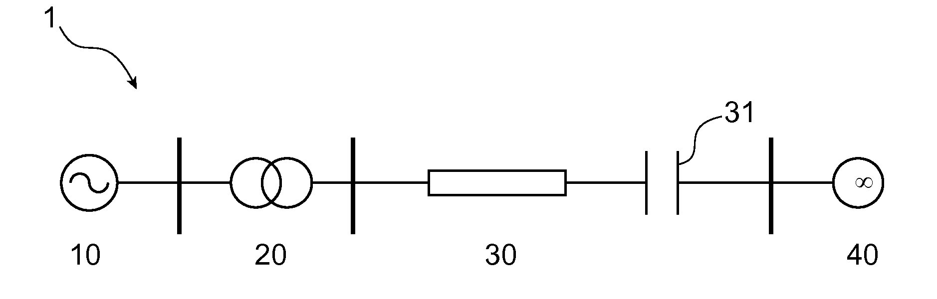
[0050]FIG. 1 illustrates a first installation 1 that comprises a power distribution system according to the invention. This installation comprises:[0051]200 MW wind farm 10,[0052]a point of common coupling transformer 20 connected to the 200 MW wind farm,[0053]a 200 km series compensated transmission line 30 of 230 kV at which the 200 MW wind farm is radially connected to the 200 MW wind farm thanks to the point of common coupling transformer 20, the transmission line 30 comprising a series capacitor 31 with a bypass switch that is not illustrated,[0054]a shunt flexible alternating current transmission systems apparatus, not illustrated, of STATCOM type that is connected at the point of common coupling,[0055]a damping controller that is designed to modulate the voltage reference of the AC voltage controller of the shunt flexible alternating current transmission systems apparatus.

[0056]In this installation 1, the damping controller input c...

example 2

A Complex Installation as Illustrated in FIG. 3

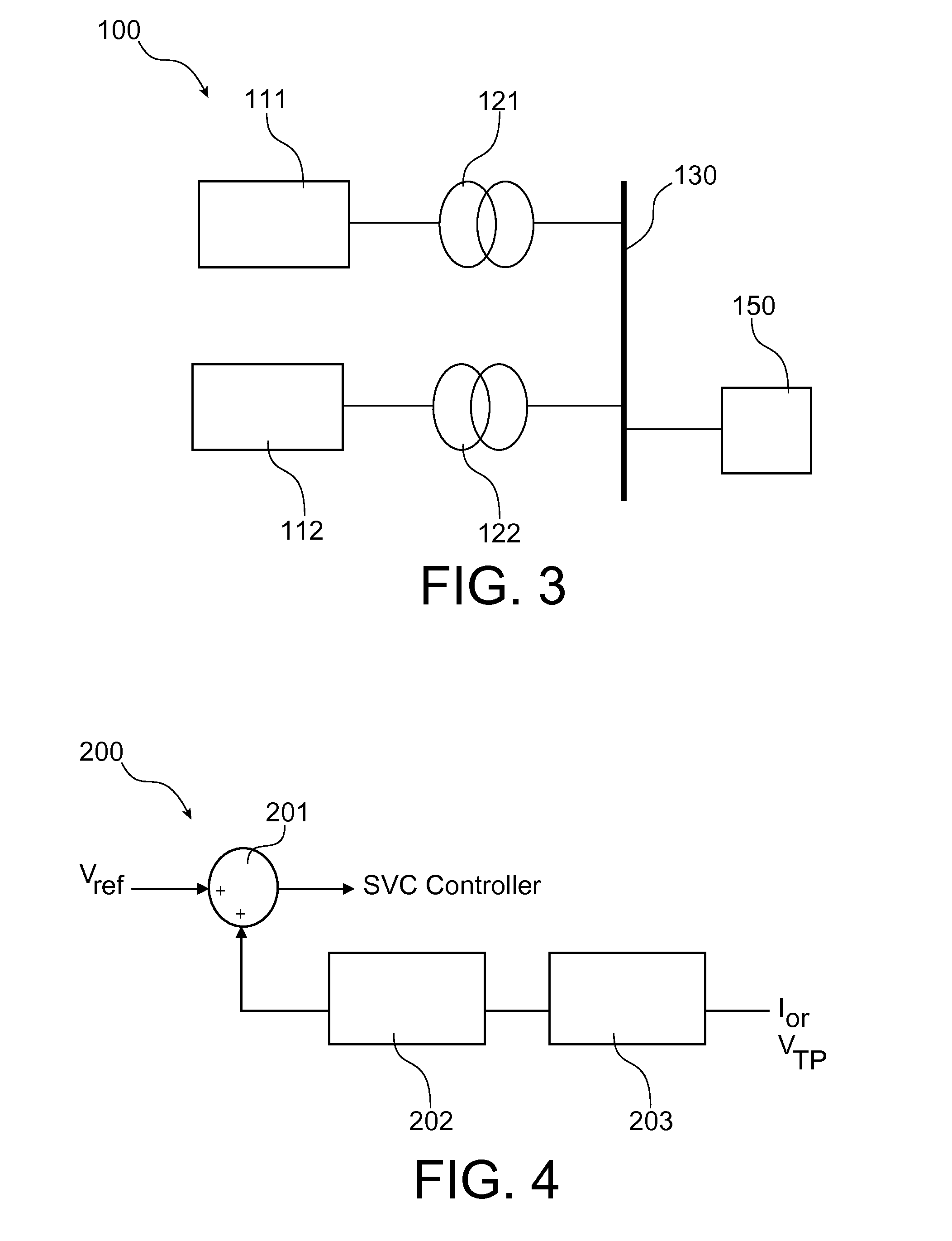
[0059]FIG. 3 illustrates a second installation 100 that comprises a power distribution system according to the invention. This installation 100 comprises:[0060]a first wind farm 111 that comprises doubly fed induction wind generators,[0061]a first point of common coupling transformer 121 connected to the first wind farm 111,[0062]a 345 kV point of common coupling 130 of a high voltage bus that is connected to the first point of common coupling transformer 121,[0063]a static VAR compensator 150 that is installed at the high voltage 345 kV point of common coupling 130, the static VAR compensator 150 comprising at least a capacitor,[0064]a second wind farm 112 that comprise wound rotor with external resistor wind generators,[0065]a second point of common coupling transformer 122 that connects the second wind farm to the 345 kV point of common coupling.

[0066]The first and the second wind farm form respectively a first and a second power gen...


PUM


Abstract

A power distribution system comprising a point of common connection that receives electric power supplied by a first power generation system and a second generation system, with the second power generation system that comprises a renewable electric power generator; a transmission line operatively connected to the point of common connection for conducting the electric power between the point of common connection and an external AC electric network. The power distribution furthermore comprises a capacitive compensator connected in series with the transmission line to compensate for a reactive power component of the electric power conducted by the transmission line; and a shunt arranged flexible AC transmission system that mitigates a sub-synchronous resonance effect caused at least in part by the capacitive compensator. A flexible AC transmission system controller of the flexible AC transmission system comprises a damping effect on sub-synchronous oscillations included in the sub-synchronous resonance.

Description

TECHNICAL FIELD[0001]The invention relates to electricity transmission and more precisely to power distribution systems used for the transmission of electricity power.PRIOR ART[0002]Concerning power distribution systems that connect wind farm generators, sub-synchronous resonance phenomena have been identified as a potential problem where transmission lines are compensated with series capacitor banks where potential damage may occur in power plant generators. The subject was first identified in the early 1970s and has gained more prominence in recent years with the increased application of series capacitor banks for transmission line optimization. This is especially true now in the case of renewable energy integration where multiple series capacitor banks are utilized near wind farm generators.[0003]The frequency sub-synchronous resonance range is defined as inferior to the fundamental frequency that is usually 60 Hz.[0004]The sub-synchronous resonances may come from interactions be...

Claims


Application Information

Patent Timeline
IPC IPC(8): H02J3/24
CPCH02J3/24H02J3/1807Y02E40/30H02J3/00125H02J2300/28H02J3/381Y02E10/76H02J3/241H02J3/50
Inventor CHOPRA, RAJIVMENDIS, REGINALDFURYK, MAREK
Owner ALSTOM TECH LTD
Why Eureka
Try Eureka