Lighting device and lighting control method

a technology of lighting control and led chips, which is applied in the direction of semiconductor devices for light sources, lighting and heating apparatus, light source combinations, etc., can solve the problems of uneven operation voltage of each led chip, and achieve the effect of improving optical efficiency and color rendering properties

Inactive Publication Date: 2014-09-04
LG INNOTEK CO LTD
View PDF9 Cites 27 Cited by
  • Summary
  • Abstract
  • Description
  • Claims
  • Application Information

AI Technical Summary

Benefits of technology

[0048]A lighting device and a lighting control method according to the embodiment cause the color coordinate of light emitted a white light emitting device to be located on a black body radiation curve within a 1931 CIE chromaticity diagram, and then provide white light similar to natural light. As a result, optical efficiency and color rendering property can be more improved.

Problems solved by technology

However, an operating voltage of each of the LED chips is not uniform and the output of each of the LED chips is changed according to an ambient temperature, so that the color coordinate of the LED chip is changed.

Method used


Image

  • Lighting device and lighting control method
  • Lighting device and lighting control method
  • Lighting device and lighting control method

Examples


first embodiment

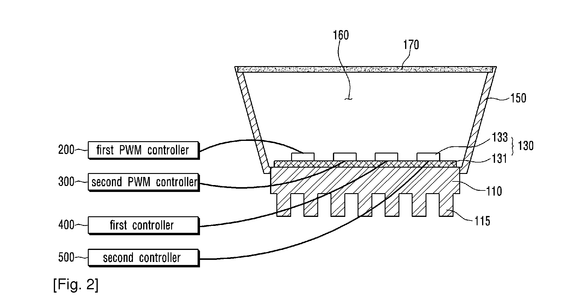
[0066]FIG. 1 is a view schematically showing a lighting device according to a first embodiment.

[0067]Referring to FIG. 1, the lighting device according to the first embodiment may include a heat sink 110, a light source 130, a reflector 150, an optical excitation plate 170, a first pulse width modulation (PWM) controller 200, a second pulse width modulation (PWM) controller 300, a first controller 400 and a second controller 500.

[0068]First, amixing chamber (without a reference numeral) is formed by the reflector 150 and the heat sink 110. The mixing chamber receives the light source 130. A mixing space 160 may be formed within the mixing chamber. The optical excitation plate 170 is disposed on the upper portion of the open mixing chamber. Here, the lights which are emitted from the light source 130 or the lights which are emitted from the light source 130 and are reflected by the reflector 150 are mixed in the mixing space 160.

[0069]The heat sink 110 may receive heat from the light...

second embodiment

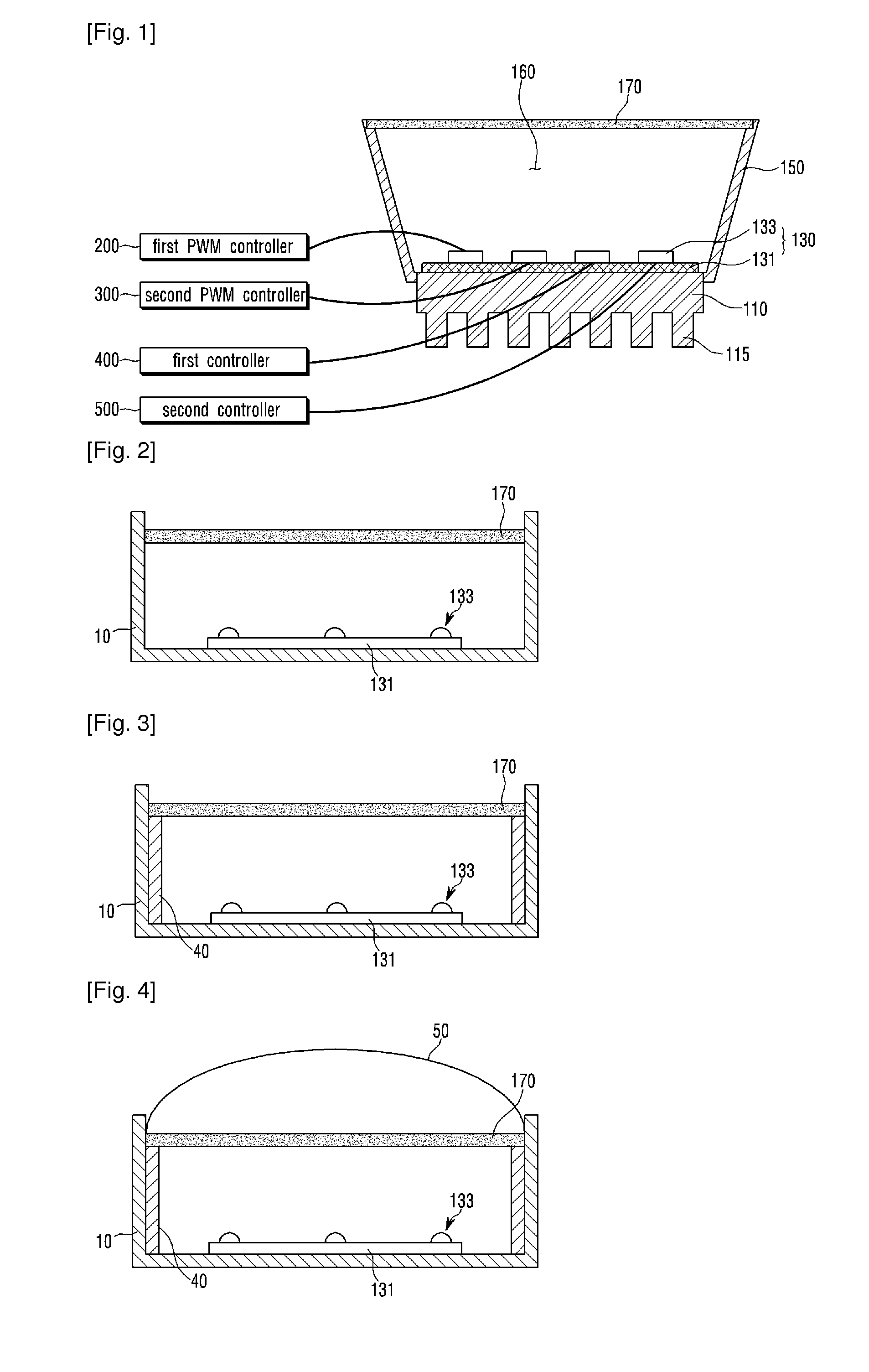
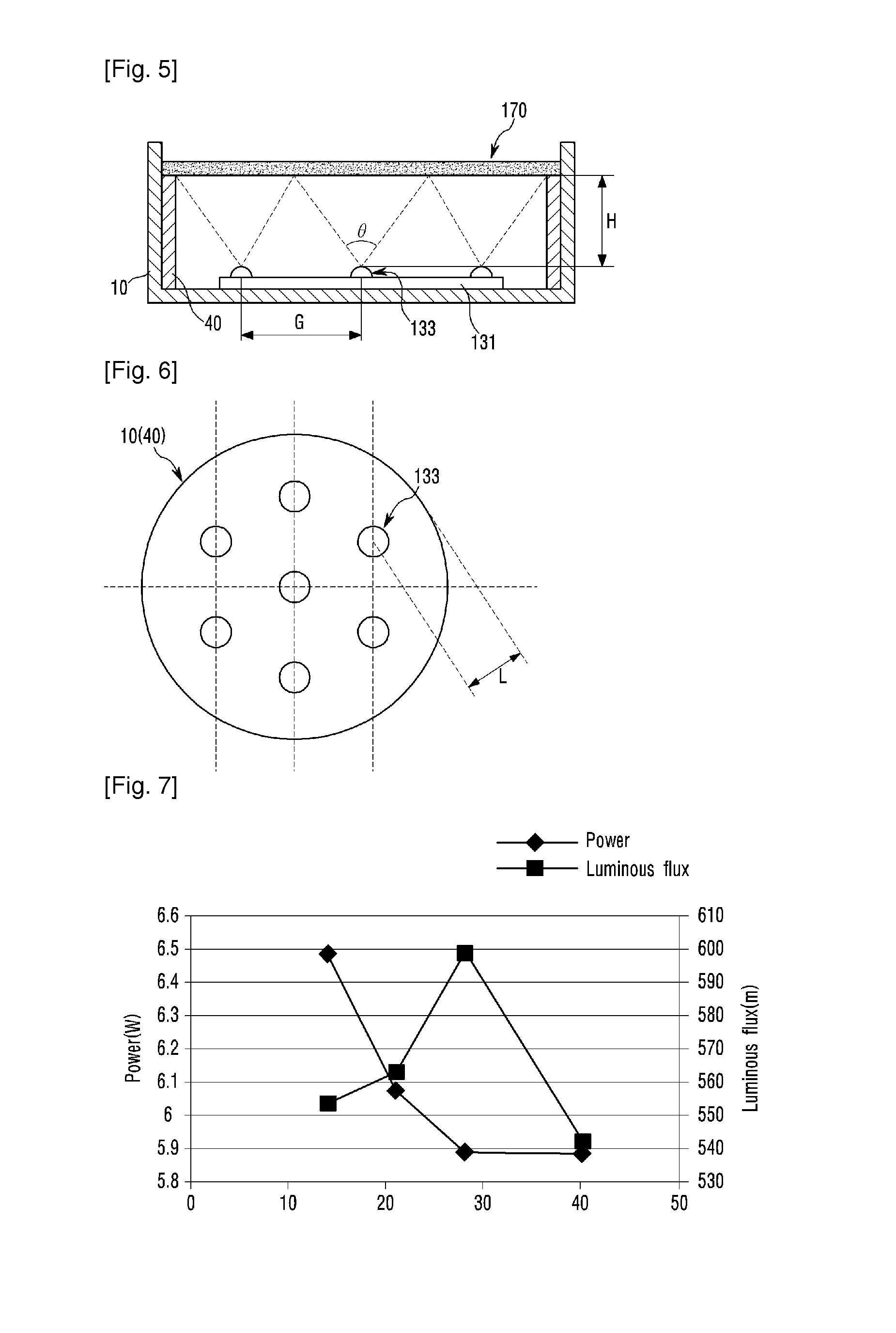
[0139]FIG. 12 is a schematic view of a lighting device according to a second embodiment. FIG. 13 is a schematic view of the lighting device including two light sources according to the second embodiment. FIG. 14 is a schematic view of the lighting device including an optical excitation plate according to the second embodiment.

[0140]Referring to FIGS. 12 to 13, the lighting device according to the second embodiment may include the heat sink 110, the light source and the reflector 150.

[0141]Also, referring to FIG. 14, the lighting device according to the second embodiment may further include the optical excitation plate 170.

[0142]Since the configurations of the heat sink 110, the reflector 150 and the optical excitation plate 170 are the same as those of the first embodiment, detailed descriptions thereof will be omitted.

[0143]Hereafter, a description of how a light emitting device is disposed will be described in detail with the second embodiment.

An Embodiment Shown in FIG. 12

[0144]R...


PUM


Abstract

A lighting device may be provided that includes: a first to a fourth light emitting devices which are disposed on a substrate a first and a second pulse width modulation controllers which perform a pulse width modulation on currents applied to the first and the second light emitting devices respectively; and a first and a second controllers which control respectively currents applied to the third and the fourth light emitting devices having color temperatures different from those of the first and the second light emitting devices, wherein an (x, y) coordinate, which is determined by the mixture of the lights emitted from the first to the fourth light emitting devices and is located within a 1931 CIE chromaticity diagram, is moved onto a black body radiation curve within the 1931 CIE chromaticity diagram through the pulse width modulation of the first and the second pulse width modulation controllers and the control of the first and the second controllers.

Description

TECHNICAL FIELD[0001]This embodiment relates to a lighting device and a lighting control method.BACKGROUND ART[0002]A white light emitting device is now increasingly used in, for example, an LCD backlight unit, a camera phone flash, an electric sign, a lighting device and the like. Therefore, many researches are now being actively devoted to the white light emitting device.[0003]A method for manufacturing the white light emitting device includes a method using a single chip and a method using multi-chips. The method using a single chip is to obtain white light by adding a phosphor on a blue LED chip or an UV LED chip. The method using multi-chips is to obtain white light by combining two or three LED chips emitting lights having mutually different wavelengths.[0004]One of the methods using multi-chips is to create white light by combining three R, G and B LED chips. However, an operating voltage of each of the LED chips is not uniform and the output of each of the LED chips is chang...

Claims


Application Information

Patent Timeline
Patent Type & Authority Applications(United States)
IPC IPC(8): H05B33/08H05B44/00
CPCH05B33/0857F21K9/62F21K9/64F21Y2113/10F21Y2113/13H05B45/24H05B45/20
Inventor KIM, YOUNG JINPARK, JONG CHANKWON, KI SOOJEONG, SEUNG BEOMSON, EON HO
Owner LG INNOTEK CO LTD
Why Eureka
Try Eureka