Ink jet recording apparatus

a recording apparatus and jet technology, applied in printing and other directions, can solve the problems of affecting the normal discharge of ink, clogging of the nozzle, poor ink discharge, etc., and achieve the effects of suppressing damage to the surface of the nozzle plate, reducing the risk of clogging, and improving image quality

Active Publication Date: 2014-09-04
SEIKO EPSON CORP
View PDF0 Cites 5 Cited by
  • Summary
  • Abstract
  • Description
  • Claims
  • Application Information

AI Technical Summary

Benefits of technology

[0028]Due to the fact that the content concentration of the inorganic pigment contained in the ink composition is 1.0% by weight or more as in this application example, an ink jet recording apparatus capable of forming an image having higher definition and excellent image quality, such as contrast, can be provided. Moreover, when the first discharge port array is wiped, the surface of the nozzle plate is sometimes damaged in the vicinity of the first discharge port array due to the fact that the inorganic pigment is pressed against the surface of the nozzle plate by the wiping member to rub the surface of the nozzle plate. However, damages to the surface of the nozzle plate are suppressed due to the effect described above even when 1.0% by weight or more of the inorganic pigment is contained as in this case.

Problems solved by technology

Since the nozzle diameter is small and the discharge energy is also small, the ink which adheres to the nozzles and undergoes an increase in viscosity cannot be eliminated, so that clogging of the nozzles is likely to occur, which sometimes results in poor ink discharge.
Furthermore, fibers, paper powder, surrounding dust, and the like generated from recording media, such as paper and cloth, sometimes adhere to the formation surface (nozzle plate surface) of nozzles, which similarly hinders normal discharge of ink.
However, the method according to JP-A-2006-142804 has had a problem in that the ink wiping properties are poor.
Specifically, the method has had a problem in that, in the case of the cleaning using the wiping blade, when ink adhering to the nozzle surface, a nozzle plate cover, or the wiping blade suffers from an increase in viscosity and dries, for example, the ink cannot be removed.
On the other hand, the method described in JP-A-2009-101630 has had a problem in that, although the wiping properties improve, a liquid repellent film formed on the surface of the nozzle plate deteriorates.
Specifically, in the case of an ink jet recording apparatus which performs recording using an ink composition containing an inorganic pigment, there has been a problem in that the inorganic pigment present between the wiping member and the surface of the nozzle plate acts on the surface of the nozzle plate to damage the liquid repellent film and the like in cleaning (in wiping).
When the liquid repellent film is damaged around an ink discharge port, ink discharge becomes unstable, which has caused a problem in that the impact position of ink droplets varies, for example.
Moreover, due to the fact that the second discharge port array is wiped in priority to the first discharge port array in a series of the wiping operations in which the surface of the nozzle plate is wiped by the wiping member, a state where the inorganic pigment is present between the wiping member and the surface of the nozzle plate is difficult to occur in a series of the wiping operations.
Thus, due to the fact that the second discharge port arrays are wiped in priority to the first discharge port arrays, the state where the inorganic pigment is present between the wiping member and the surface of the nozzle plate is more difficult to occur in a series of the wiping operations.
However, damages to the surface of the nozzle plate are suppressed due to the effect described above even in the case of using such an inorganic pigment.

Method used


Image

  • Ink jet recording apparatus
  • Ink jet recording apparatus
  • Ink jet recording apparatus

Examples


embodiment 1

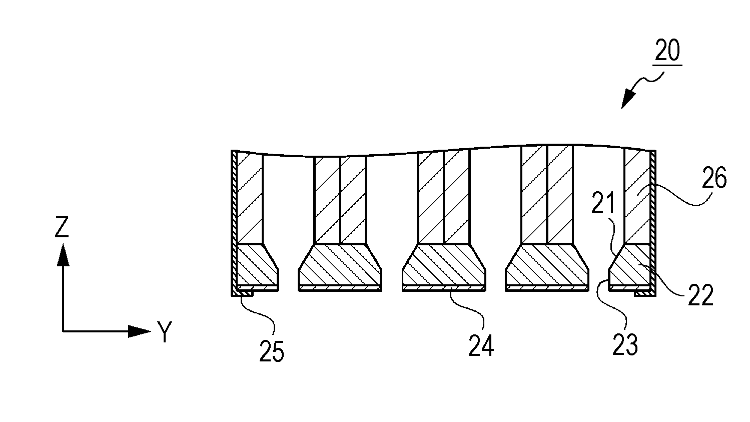
[0139]In the ink jet recording apparatus 1 according to Embodiment 1, the first discharge port arrays 50 and the second discharge port arrays 51 are arranged in such a manner that the second discharge port arrays 51 are wiped in priority to the first discharge port arrays 50 in a series of the operations in which the surface of the nozzle plate 22 is wiped by the wiping member 31. Hereinafter, a specific description is given.

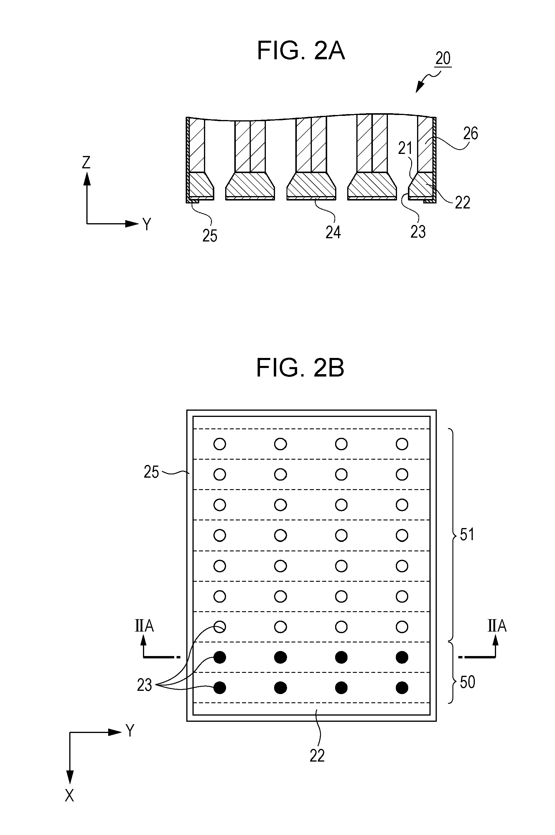
[0140]FIG. 4A is a plan view of the nozzle plate 22 (hereinafter referred to as a nozzle plate 22a) according to Embodiment 1 as viewed from the discharge port 23 side.

[0141]The nozzle plate 22a has n pieces of the first discharge port arrays 50 and m pieces of the second discharge port arrays 51. On the nozzle plate 22a, n pieces of the first discharge port arrays 50 are continuously arranged on one side (+X side in FIG. 4A) (i.e., n pieces of the first discharge port arrays 50 are continuously arranged from one end portion). On the nozzle plate 22a, m pieces o...

embodiment 2

[0153]Next, an ink jet recording apparatus 1 according to Embodiment 2 is described. In the description, the same constituent portions as those of the embodiment described above are denoted by the same reference numbers and the duplicated description is omitted.

[0154]In Embodiment 2, in n pieces of the first discharge port arrays 50 and m pieces of the second discharge port arrays 51, the number given by n+m is even, k=(n+m) / 2 is established and when the number given by n+m is odd, k=(n+m−1) / 2 is established. In such a case, in a series of the operations in which the wiping member 31 wipes the surface of the nozzle plate 22 in such a manner as to wipe the first discharge port arrays 50 or the second discharge port arrays 51 of the first array to the n+m-th array, the first discharge port arrays 50 and the second discharge port arrays 51 are arranged in such a manner that the first discharge port array 50 of the n-th array is wiped in the range of the k+1-th array to the n+m-th array...

embodiment 3

[0161]Next, the ink jet recording apparatus 1 according to Embodiment 3 is described. In the description, the same constituent portions as those of the embodiments described above are denoted by the same reference numbers and the duplicated description is omitted.

[0162]In Embodiment 3, in n pieces of the first discharge port arrays 50 and m pieces of the second discharge port arrays 51, when the number given by n+m is even, k=(n+m) / 2 is established and when the number given by n+m is odd, k=(n+m−1) / 2 is established. In such a case, in a series of the operations in which the wiping member 31 wipes the surface of the nozzle plate 22 in such a manner as to wipe the first discharge port arrays 50 or the second discharge port arrays 51 of the first array to the n+m-th array, the first discharge port arrays 50 and the second discharge port arrays 51 are arranged in such a manner that the percentage in which the first discharge port arrays 50 are wiped in the range from the first array to ...


PUM


Abstract

An ink jet recording apparatus has a first discharge port array in which discharge ports of a plurality of nozzles which discharge an ink composition containing an inorganic pigment are disposed side by side, a second discharge port array in which discharge ports of a plurality of nozzles which discharge an ink composition containing a coloring material other than the inorganic pigment are disposed side by side, a nozzle plate having the first discharge port array and the second discharge port array, a liquid repellent film provided on the nozzle plate, a wiping member which wipes the surface of the nozzle plate and has absorbability of the ink composition, in which, in a series of operations in which the surface of the nozzle plate is wiped by the wiping member, the second discharge port array is wiped in priority to the first discharge port array.

Description

[0001]Priority is claimed under 35 U.S.C. §119 to Japanese Application No. 2013-040406 filed on Mar. 1, 2013, is hereby incorporated by reference in its entirety.BACKGROUND[0002]1. Technical Field[0003]The present invention relates to an ink jet recording apparatus.[0004]2. Related Art[0005]Recording employing an ink jet recording system is performed by discharging small ink droplets and causing the small ink droplets to fly to cause the small ink droplets to adhere onto recording media, such as paper. Due to a recent innovative progress of the ink jet recording technology, an ink jet recording apparatus employing the ink jet recording system has been used also in the field of high definition image recording for which photo and offset printing have been used until now.[0006]In the ink jet recording apparatus, when moisture and other volatile components contained in ink to be discharged evaporate, the viscosity of the ink increases. In recent ink jet recording, in order to perform hi...

Claims


Application Information

Patent Timeline
Patent Type & Authority Applications(United States)
IPC IPC(8): B41J2/165
CPCB41J2/16535B41J2002/1655
Inventor FUKUDA, MASAKOSAYAMA, TOMOHIROKASAHARA, SHOKI
Owner SEIKO EPSON CORP
Why Eureka
Try Eureka