Wide Area Imaging System and Method

a wide area imaging and wide area technology, applied in the field of wide area, can solve the problems of expensive peripheral window, inefficient use of pixels, expensive commercial applications, etc., and achieve the effect of selectively controlling or varying the wide area image, and fast and continuous wide area images

Active Publication Date: 2014-09-04
DIVERSIFIED INNOVATIONS FUND LLLP
View PDF3 Cites 26 Cited by
  • Summary
  • Abstract
  • Description
  • Claims
  • Application Information

AI Technical Summary

Benefits of technology

[0023]It should also be noted that the present invention overcomes the difficulties described above by using a low cost sensor with sufficient pixels for the application but overcomes the limitations of sensitivity and speed by way of a digitally controlled servo system (that controls the motorized step and dwell sequence) that accommodates the need for variable or programmable integration times while providing motion adequate to form a wide area image quickly and continuously, and to selectively control or vary the wide area image in real time.

Problems solved by technology

These are sometimes used in scenario (1) above, but require many FPA's, thereby making this scenario costly and less reliable for commercial applications.
When these devices are used for scenario (3), they are inefficient in the use of pixels and also require an expensive peripheral window, both of which push cost upwards.
The use of uncooled microbolometer FPAs continuously scanning a wide area can provide a low cost means of imaging, but the imaging speed is too low for real-time applications, owing to the low sensitivity, e.g., D*, of such thermal devices (as compared to cooled photonic devices) and the typically low sampling rate required by pixel thermal mass constraints.
Thus even with a relatively low cost technology (uncooled microbolometers) it is yet relatively expensive to obtain a 360 degree field of view.
The resultant wide area imaging system can be very effective, but even with a good tradeoff in the choice of sensor technology and the number of pixels used, the overall solution has a relatively low mean time to failure which makes it expensive to maintain and the systems components are quite expensive, often much more expensive than the aforementioned multiple-FPA approach for uncooled microbolometers devices.
Such assemblies can be made to work with the invention, but will not be as broadly optimal as the direct drive servo motor implementation.

Method used


Image

  • Wide Area Imaging System and Method
  • Wide Area Imaging System and Method
  • Wide Area Imaging System and Method

Examples


Embodiment Construction

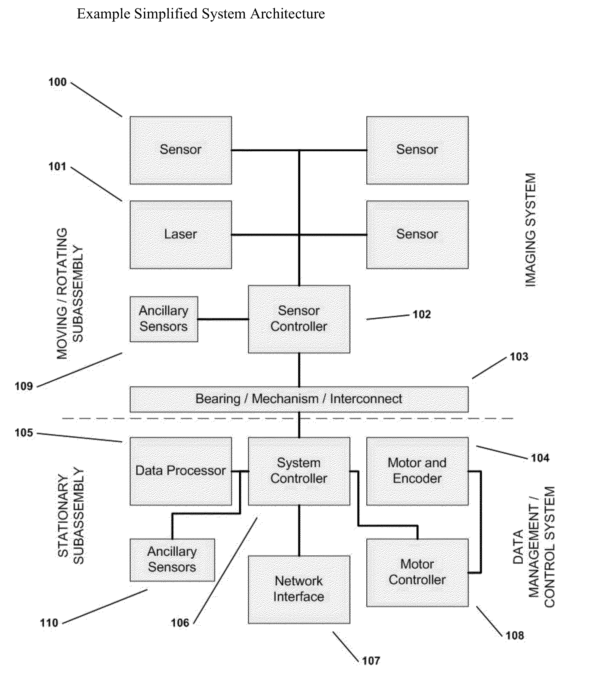
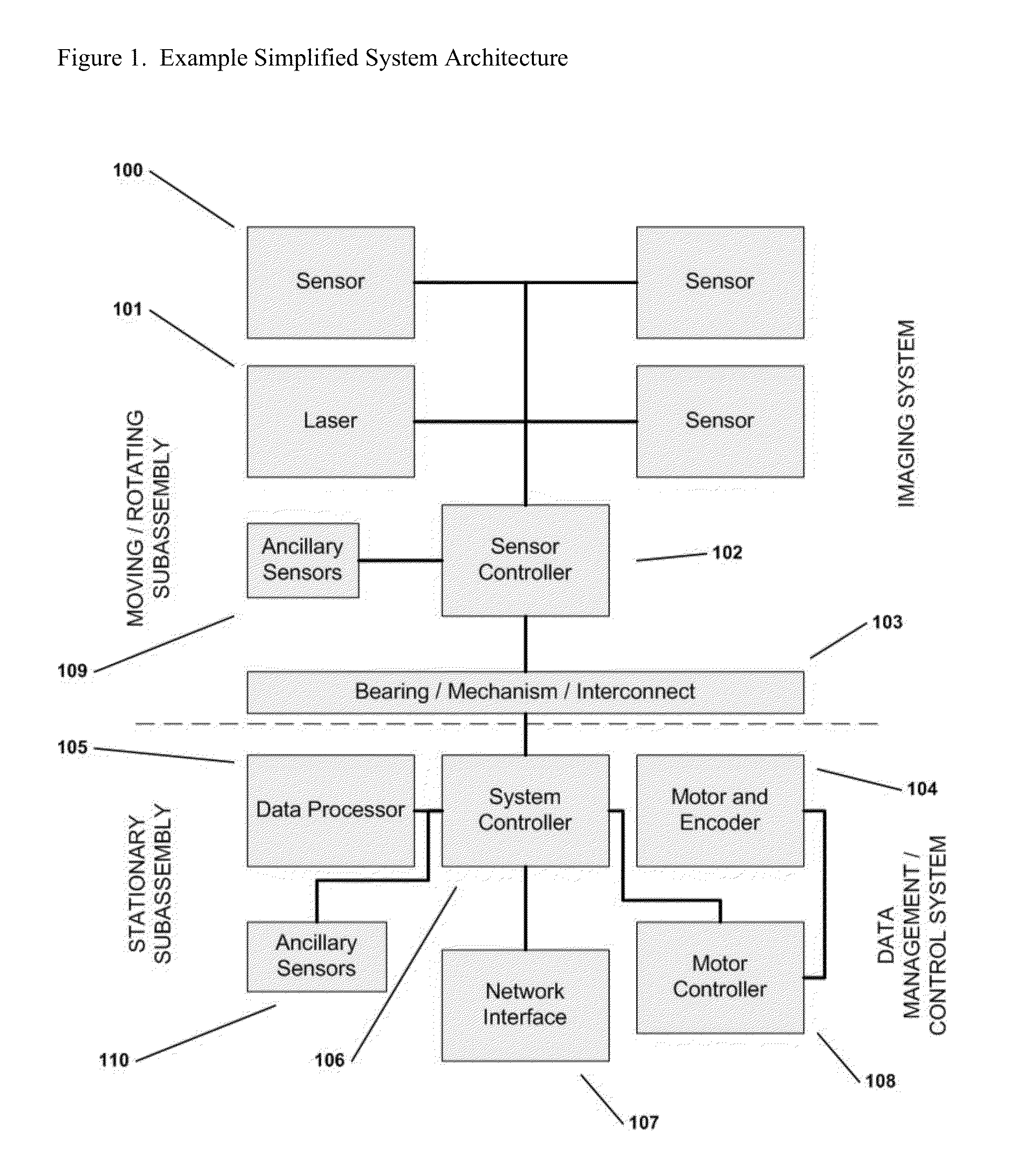
[0032]As discussed above, the present invention relates to a new and useful paradigm in wide area imaging, including panoramic imaging, in which the wide area imaging is provided by a step / dwell / image capture, and as needed image stitch, process to capture images and produce from the captured images a wide area image. The image capture is by a sensor that has a predetermined image field and provides image capture at a predetermined frame capture rate, and by a motorized step and dwell sequence of the sensor, where image capture is during a dwell period or interval, and the step and dwell sequence of the sensor is synchronized with the image capture rate of the sensor. In addition, an image stitch is processor controlled and designed to combine images captured by the sensor in a predetermined manner to produce the wide area image.

[0033]The principles of the present invention are described herein in connection with one exemplary system and method, and from that description the manner ...


PUM


Abstract

The present invention provides a new and useful paradigm in wide area imaging, in which wide area imaging is provided by a step/dwell/image capture process and system to capture images and produce from the captured images a wide area image. The image capture is by a sensor that has a predetermined image field and provides image capture at a predetermined frame capture rate, and by a motorized step and dwell sequence of the sensor, where image capture is during a dwell, and the step and dwell sequence of the sensor is synchronized with the image capture rate of the sensor.

Description

RELATED APPLICATION / CLAIM OF PRIORITY[0001]This application is related to and claims the priority of Provisional Application No. 61 / 722,120, filed Nov. 2, 2012, and entitled Multi Sensor Panoramic Camera; and which provisional application is incorporated by reference herein.BACKGROUND[0002]The invention relates to the field of wide area, or, when imaged regions are all contiguous, panoramic imaging. The invention has particular utility for commercial security and surveillance but is readily used for other applications that require a low cost wide field of view device, particularly mid-wave and long-wave thermal infrared (MWIR, LWIR respectively).[0003]There are at least three ways to obtain a wide area image, including a 360 degree panorama, with a focal plane array (FPA): 1) use multiple copies of the FPA each having its own lens and field of view, and assign each of the FPAs to a particular segment of the wide area; 2) use projection optics to map pixels around the periphery to a ...

Claims


Application Information

Patent Timeline
Patent Type & Authority Applications(United States)
IPC IPC(8): H04N5/232
CPCH04N5/23238H04N23/58H04N23/698H04N23/11
Inventor GRIFFIS, ANDREW J.POWELL, MICHAEL B.HOWELL, MARK J.
Owner DIVERSIFIED INNOVATIONS FUND LLLP
Why Eureka
Try Eureka