
LED lighting device including heat dissipation structure and method for making the same

Inactive Publication Date: 2014-09-04
SENGLED OPTOELECTRONICS
View PDF4 Cites 19 Cited by
  • Summary
  • Abstract
  • Description
  • Claims
  • Application Information

AI Technical Summary

Benefits of technology

The LED lighting device has both an internal and external cooling system to help reduce the device's temperature and extend its lifespan. This is done by creating a ventilation gap and a channel within the lamp holder for air circulation. This also helps protect human hands from being burned when touching the lamp cup.

Problems solved by technology

However, the heat dissipation lamp cup may have already held heat generated due to the operation of the device.
It may then be difficult to effectively dissipate heat from the LED lighting device.
Consequently, overtime, electronic components of the driving power supply may not work properly, which may affect the lifespan of the LED lighting device.

Method used


Image

  • LED lighting device including heat dissipation structure and method for making the same
  • LED lighting device including heat dissipation structure and method for making the same
  • LED lighting device including heat dissipation structure and method for making the same

Examples


Embodiment Construction

[0018]Reference will now be made in detail to exemplary embodiments of the disclosure, which are illustrated in the accompanying drawings. Wherever possible, the same reference numbers will be used throughout the drawings to refer to the same or like parts.

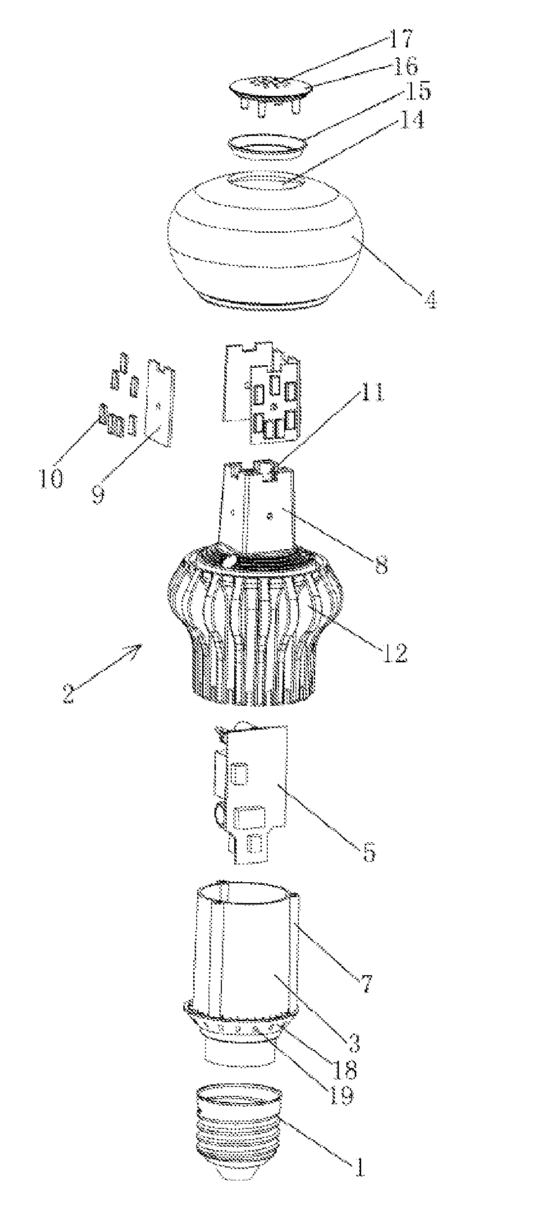
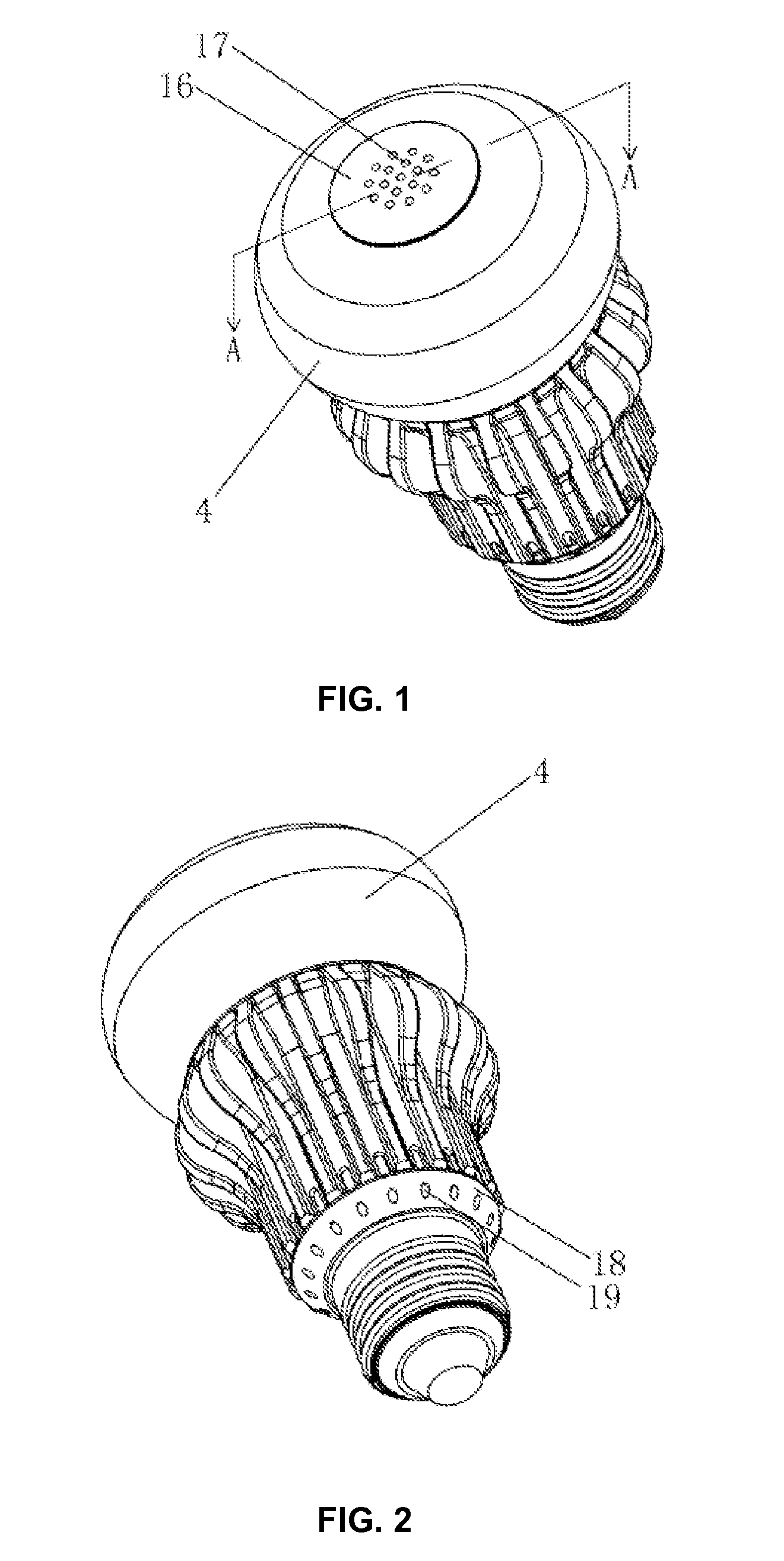
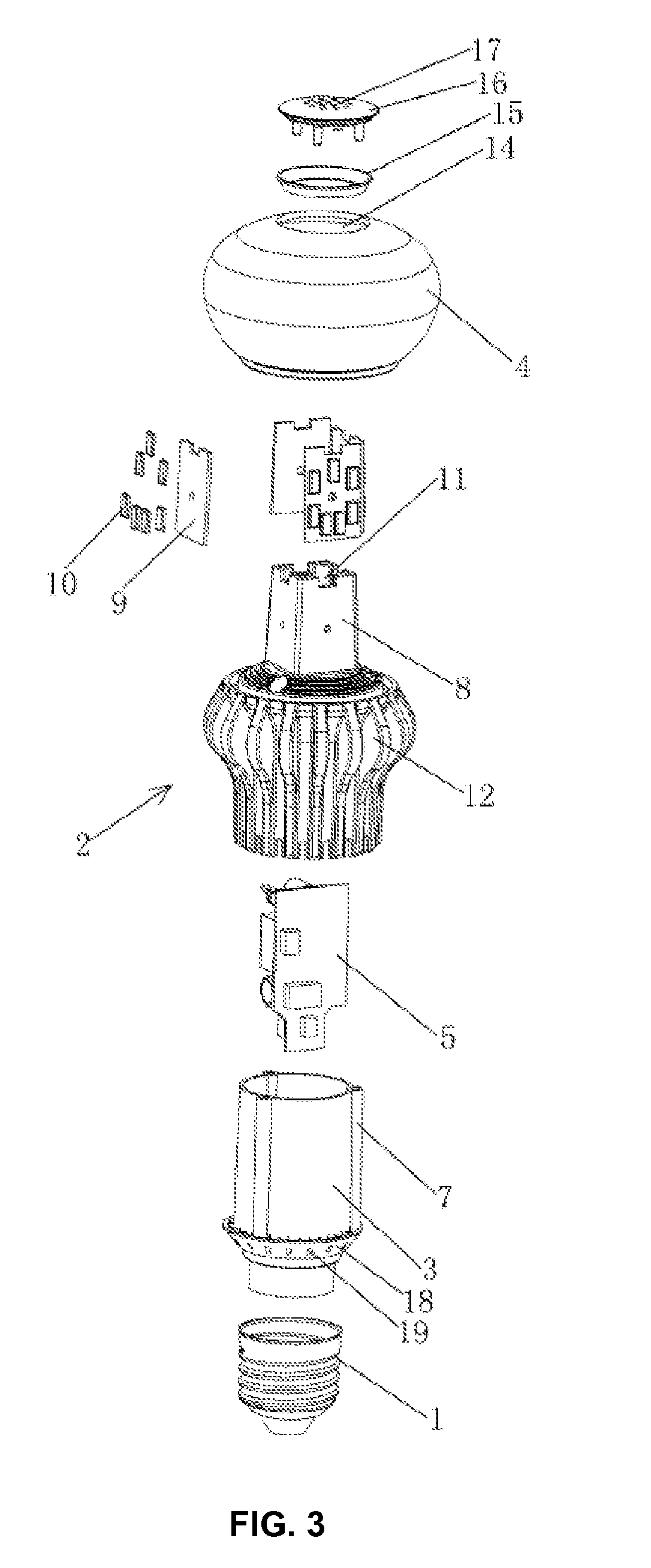
[0019]Disclosed herein provides an LED lighting device including a heat dissipation structure that provides an internal cooling passage and an external cooling passage. The internal cooling passage can internally vent away at least a portion of the heat generated by a driving power supply and LED light source(s). The external cooling passage can include heat dissipation of at least a portion of the heat generated by the LED light sources through a heat dissipation lamp cup to the ambient environment by nature convection.

[0020]In this manner, the temperature of the heat dissipation lamp cup can be effectively reduced and would not burn human's hands when touched. In addition, the driving power supply can be cooled in embodiments co...


PUM

PropertyMeasurementUnit
Angleaaaaaaaaaa
Lengthaaaaaaaaaa
Shapeaaaaaaaaaa

Abstract

LED lighting devices and fabrication methods are provided. An LED lighting device includes a heat dissipation lamp cup including a hollow structure, a driving power supply casing socket configured within the heat dissipation lamp cup to form a ventilation gap between the driving power source casing and an inner wall of the heat dissipation lamp cup, and a lamp holder configured on top of the heat dissipation lamp cup. The lamp holder includes one or more sidewalls forming a ventilation channel passing through the lamp holder. The ventilation channel is connected to the ventilation gap for air circulation. The LED lighting device also includes a substrate configured on an outer surface of each of the one or more sidewalls of the lamp holder and a plurality of LED light sources mounted on the substrate.

Description

CROSS-REFERENCES TO RELATED APPLICATIONS[0001]This application is a continuation in part of PCT application No. PCT / CN2012 / 073361, filed on Mar. 31, 2012, which claims the priority of Chinese Patent Application No. 201110380199.1, filed on Nov. 25, 2011, the entire contents of all of which are incorporated herein by reference.FIELD OF THE DISCLOSURE[0002]The present disclosure relates to the field of light emitting diode (LED) technology and, more particularly, relates to an LED lighting device including a heat dissipation structure and fabrication method of the LED lighting device.BACKGROUND[0003]Cooling of an LED lighting device is important for stable operations and high quality of LED lighting devices. Conventionally, cooling of the LED lighting devices mainly focus on cooling of LED light sources, for example, by improving the shape, structure, and material quality of a heat dissipation lamp cup to optimize the cooling performance. Often, the cooling of the driving power supply...

Claims


Application Information

Patent Timeline
IPC IPC(8): F21V29/00F21K99/00
CPCF21V29/004F21K9/90F21K9/00F21V29/83F21V23/009F21V29/506F21V29/773F21V3/02F21K9/23F21Y2115/10F21Y2107/00Y10T29/4913F21V29/74
Inventor CHEN, FANGSHEN, JINXIANG
Owner SENGLED OPTOELECTRONICS
Learn More