
Rapid in-the-field auto-alignment for radio frequency and free-space optical data communication transceivers

a radio frequency and optical data communication technology, applied in the field of radio frequency and free space optical data communication transceivers, can solve the problems of affecting the transmission quality of the transmission, and the transmission performance of the e-band data transmission, so as to achieve the effect of high carrier availability

Active Publication Date: 2014-09-04
EOS DEFENSE SYST USA INC
View PDF26 Cites 24 Cited by
  • Summary
  • Abstract
  • Description
  • Claims
  • Application Information

AI Technical Summary

Benefits of technology

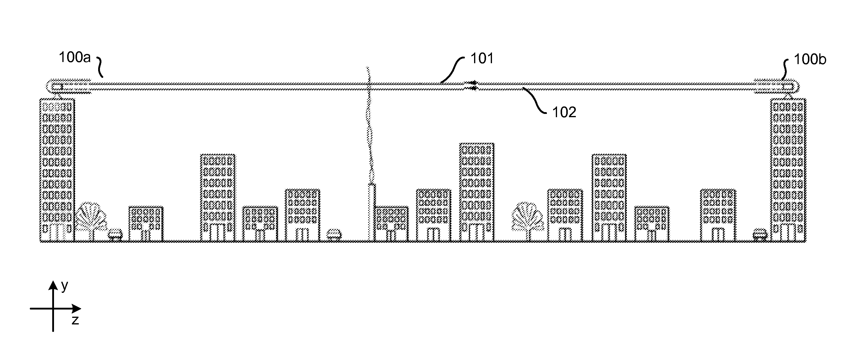
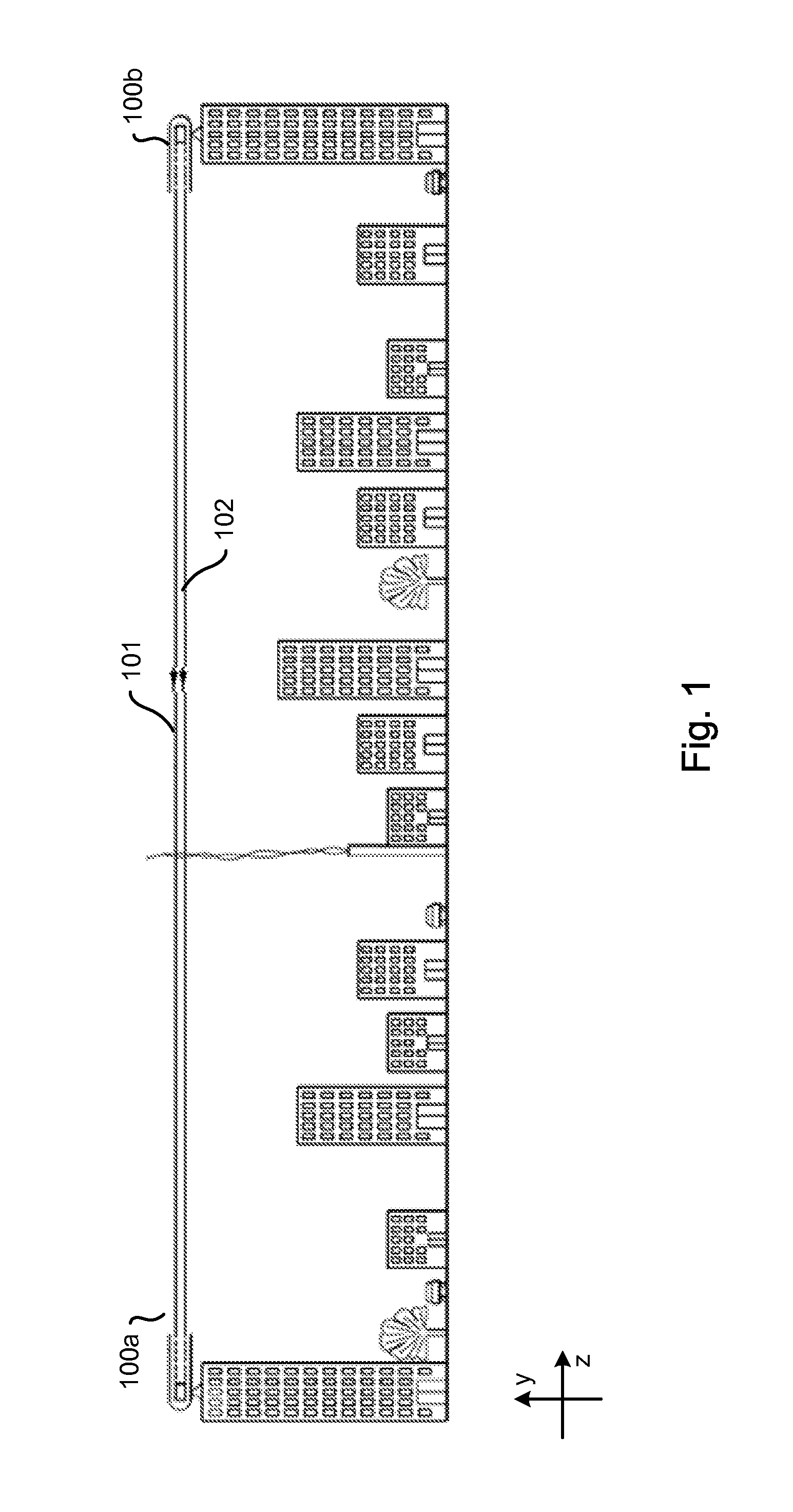
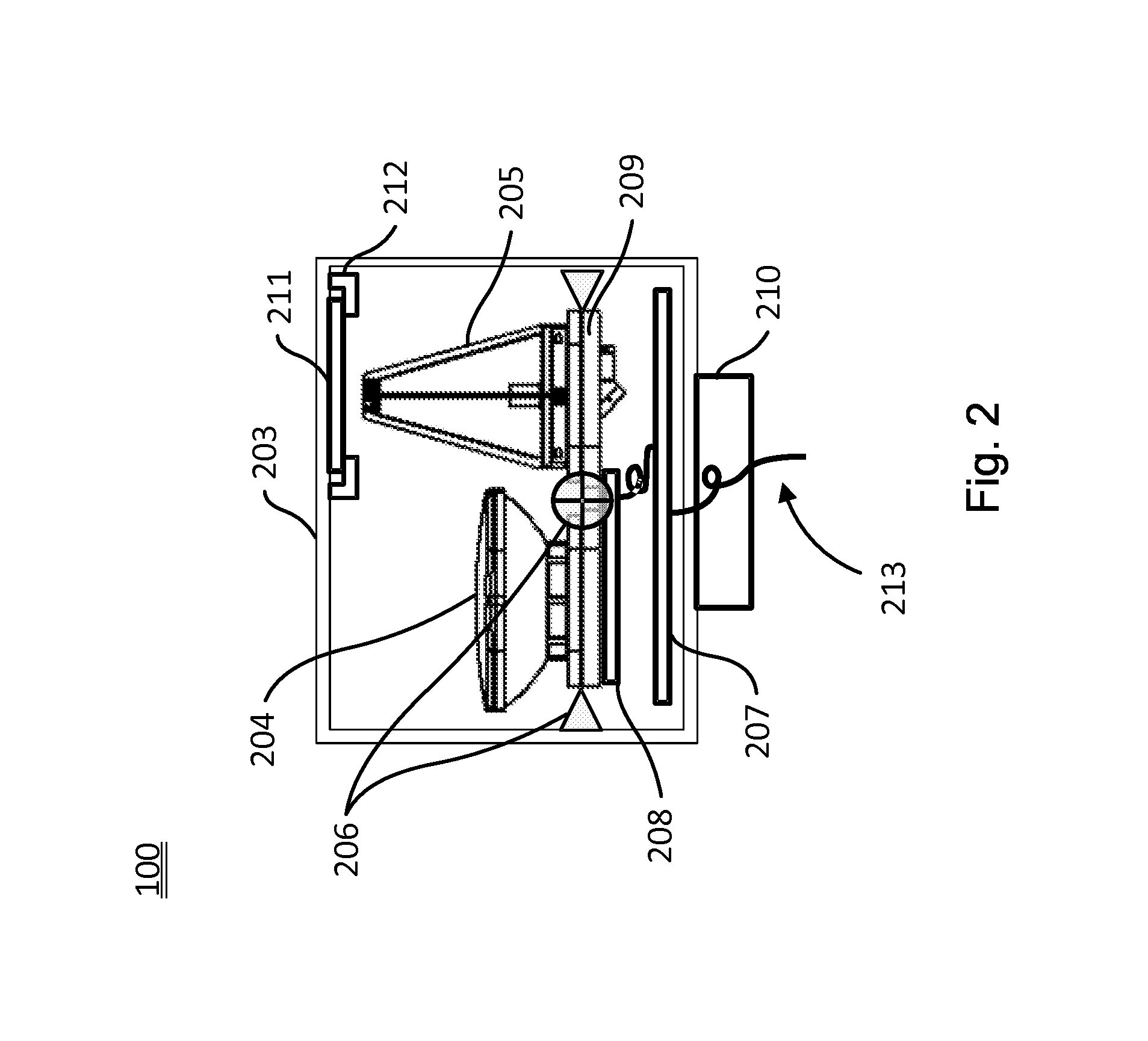
This patent describes an integrated apparatus that combines millimeter wave (mmW) and free space optical (FSO) data transmission on a stabilized assembly. The apparatus ensures high level of carrier availability and remains operational even under stressing environmental conditions. It also ensures that a mmW RF control back channel remains operational in the event of a simultaneous failure of both the RF and FSO data transmission links. The apparatus requires a high degree of alignment between local and remote combined apparatuses, which is initially provided by the mmW RF transceiver and then fine alignment is performed by the FSO transceiver. The alignment mechanism can also correct for environmental effects that would otherwise disrupt communication by either of the apparatuses.

Problems solved by technology

E-band data transmission, however, is susceptible to degraded performance due to rain.
Rain interferes with radio wave transmission in the E-band such that during a rain storm, data transmission would necessitate repeated data retransmission at best or interrupted service at worst.
FSO transmission is, however, subject to disruptions due to fog, snow, airborne particulate matter, and atmospheric turbulence.
Further, twist and sway movements due to wind and other weather can easily disrupt both E-band and FSO data transmission versus data transmissions that occurs at lower frequencies.

Method used


Image

  • Rapid in-the-field auto-alignment for radio frequency and free-space optical data communication transceivers
  • Rapid in-the-field auto-alignment for radio frequency and free-space optical data communication transceivers
  • Rapid in-the-field auto-alignment for radio frequency and free-space optical data communication transceivers

Examples


Embodiment Construction

General Overview and Benefits

[0027]An integrated communication apparatus may be used as part of a commercial communications network to facilitate the exchange of fully duplexed data with another similar device. The apparatus is configured to maintain high carrier availability, or uptime, even in adverse weather conditions. The apparatus includes two transceivers, a millimeter wave (mmW) Radio Frequency (RF) transceiver, and a Free Space Optical (FSO) transceiver. In one embodiment, the mmW RF transceiver operates in the E-band RF range, for example 13 GHz of spectrum in the 70 GHz and 80 GHz radio frequency bands. In other embodiments, the mmW RF transceiver is capable of operating outside the E-band RF range. The mmW RF transceiver may be used to transmit data and / or establish a link with an adjacent apparatus.

[0028]The auto-alignment and tracking method is designed for use with the integrated communications apparatus to allow for efficient link acquisition, using an inertially sta...


PUM


Abstract

A local communications apparatus is aligned with a remote apparatus, each apparatus comprising radio frequency (RF) and free space optical (FSO) transceivers with substantially parallel boresight. Coarse alignment is performed using the RF transceiver and fine alignment is performed using the FSO transceiver. A patterned search is performed to locate the RF signal from the remote apparatus and known features of the intensity profile are utilized to locate the global maximum, thus coarsely aligning the pair of apparatuses. A second patterned search is performed to locate the FSO signal from the remote apparatus and an iterative step-search is used to align the FSO signal centroid with the FSO transceiver, thus finely aligning the pair of apparatuses.

Description

CROSS-REFERENCE TO RELATED APPLICATIONS[0001]This application claims the benefit of U.S. Provisional Patent Application No. 61 / 771,835, entitled “Rapid In-The Field Auto-Alignment For Radio Frequency And Free-Space Optical Data Communication Transceivers,” filed on Mar. 2, 2013, which is hereby incorporated by reference in its entirety.BACKGROUND[0002]1. Field of Invention[0003]This application relates to both radio frequency as well as free space optical data communication, particularly to transceiver alignment.[0004]2. Description of the Related Arts[0005]In 2003, the FCC-licensed for use 13 GHz of spectrum in the 70 GHz and 80 GHz bands, also known as the E-band millimeter wave Radio Frequency (RF) spectrum. Ten bands in this spectrum were made commercially available for a broad range of fixed wireless applications operating at gigabit data transfer rates. Applications include point-to-point local wireless networks and broadband internet access. Communication of data through E-ba...

Claims


Application Information

Patent Timeline
Patent Type & Authority Applications(United States)
IPC IPC(8): H04B10/11
CPCH04B10/11H04B10/1125
Inventor SAINT GEORGES, ERIC
Owner EOS DEFENSE SYST USA INC
Learn More