Power supply device

Inactive Publication Date: 2014-09-04
YAZAKI CORP
View PDF2 Cites 6 Cited by
  • Summary
  • Abstract
  • Description
  • Claims
  • Application Information

AI Technical Summary

Benefits of technology

[0012]According to the present invention, the connections between the electrodes in respective pairs and the acquisition of the information on the voltages thereon can be achieved by the substrate, the electrode connecting portion and the electrically conductive portion. That is, the number of the components can be reduced compared with the conventional technique. Components required for every connection

Problems solved by technology

This unnecessarily causes the power sup

Method used


Image

  • Power supply device
  • Power supply device
  • Power supply device

Examples


first embodiment

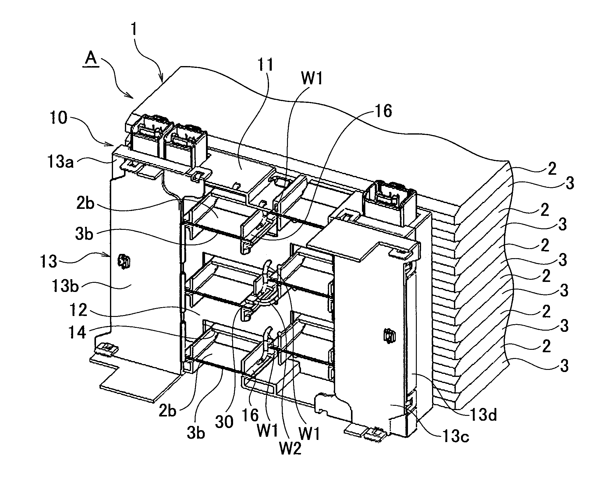
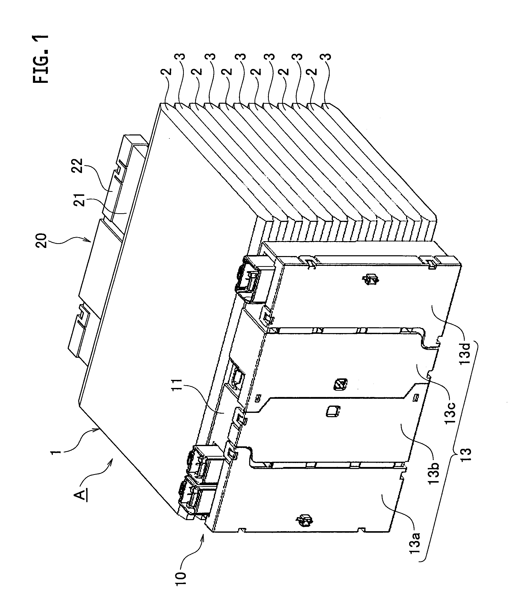
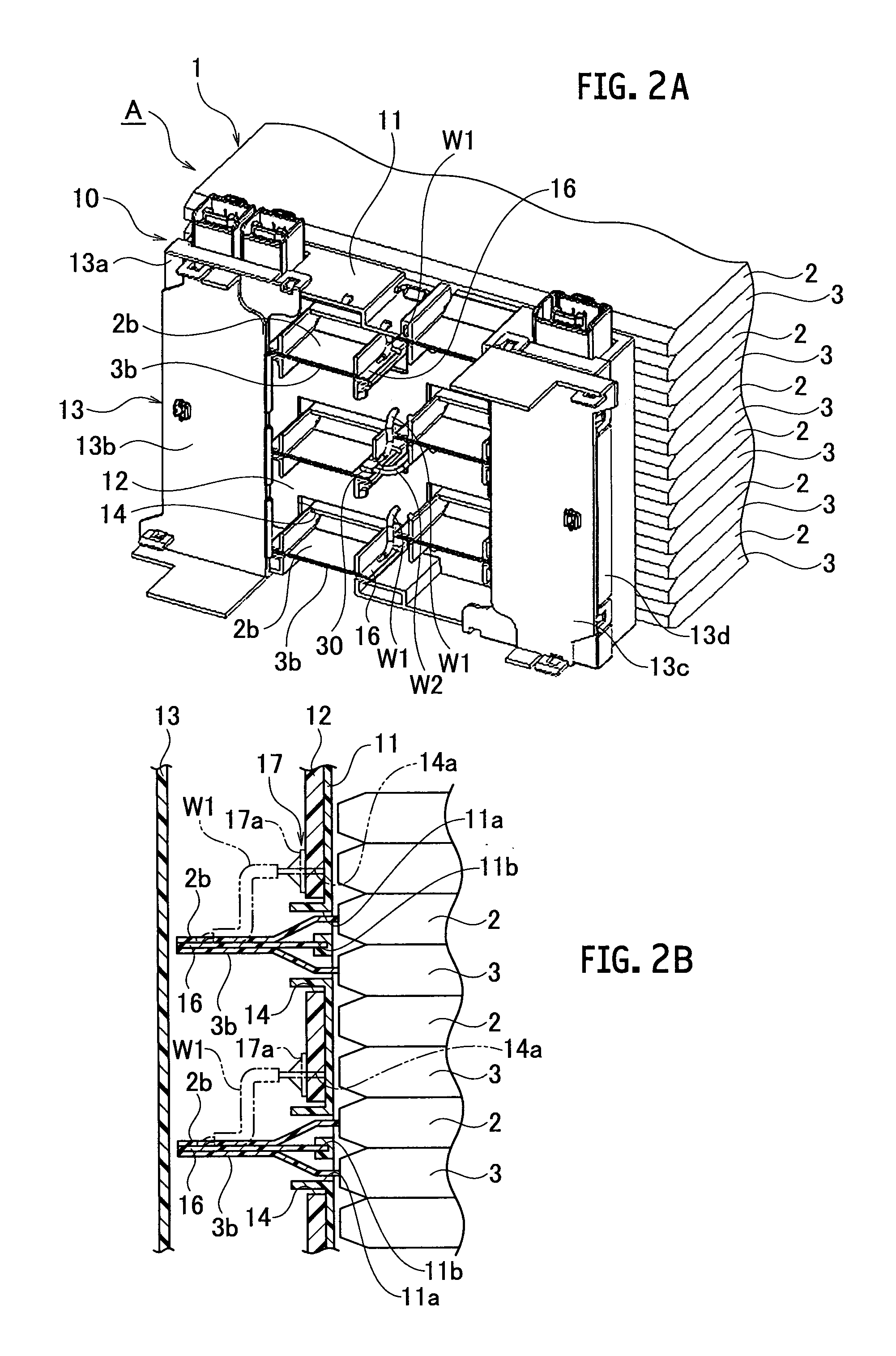
[0024]FIGS. 1 to 6 illustrate a first embodiment of the present invention. As illustrated in FIGS. 1 and 2A, a power supply device A comprises: a battery assembly 1 including stacked battery cells 2 and 3 (total twelve cells in this embodiment, for example); and a pair of battery linking bodies 10 and 20 disposed on both sides of the battery assembly 1.

[0025]As illustrated in FIG. 3 in detail, the battery assembly 1 comprises twelve battery cells 2 and 3. Hereinafter, the battery cell 2 is referred to a first battery cell 2, and the battery cell 3 is referred to a second battery cell 3. The first battery cell has electrodes 2b, and the second battery cell has electrodes 3b. The positions of the electrodes 2b and 3b are different to each other.

[0026]As illustrated in FIG. 4A, the first battery cell 2 includes a battery cell main body 2a formed into a rectangular and flat shape, a pair of electrodes (i.e. positive and negative electrodes) 2b and 2b respectively protruding from left an...

second embodiment

[0044]FIGS. 7 and 8 illustrate a second embodiment of the present invention. The second embodiment is different from the first embodiment only in structures of the electrode connecting portion and the electrically conductive member.

[0045]As illustrated in FIGS. 7 and 8, a terminal 18 for electrode is served as the electrode connecting portion as described above. The terminal 18 is formed as a part of the bus bar. A tab 19 is served as the electrically conductive member as described above. The tab 19 is integrally formed with the terminal 18 by bending a part of the bus bar. The tab 19 has a bent portion, and is formed into a shape which is easily elastically deformable. As similar to the wire W1 of the first embodiment, a tip end of the tab 19 is connected to the land (not shown) for electrode of the circuit pattern in the substrate 12.

[0046]Since other configurations of the second embodiment are the same as those of the first embodiment, the description thereof are omitted to preve...


PUM


Abstract

A power supply device comprises: a battery assembly including stacked battery cells, the battery cells having electrodes, the electrodes of the adjacent battery cells being placed opposite to one another; and a battery linking body disposed on a side at which the electrodes of the battery assembly protrude, the battery linking body being configured to cover the protruding electrodes, the battery linking body including: a terminal connected to the electrodes placed opposite to one another, and a circuit pattern for voltage detection, the circuit pattern being connected to the terminal by a electrically conductive portion.

Description

CROSS REFERENCE TO RELATED APPLICATIONS[0001]This application is a continuation application of International Application No. PCT / JP2012 / 007294, filed on Nov. 14, 2012, which claims priority to Japanese Patent Application No. 2011-250500, filed on Nov. 16, 2011, the entire contents of which are incorporated by references herein.BACKGROUND OF THE INVENTION[0002]1. Field of the Invention[0003]The present invention relates to a power supply device having stacked battery cells.[0004]2. Description of the Related Art[0005]Hybrid vehicles, electric vehicles and the like have a power supply device as a power source for driving an electric motor. Patent Application JP 2010-55885 A discloses such a power supply device as a conventional one. As shown in FIGS. 9 and 10, this power supply device 50 includes a battery assembly 51. The battery assembly 51 has stacked battery cells 52 that are arranged in two rows. Each battery cell 52 has a pair of electrodes (i.e. positive and negative electrodes...

Claims


Application Information

Patent Timeline
IPC IPC(8): H01M10/48H01M50/209H01M50/503H01M50/519H01M50/569
CPCH01M10/482H01M10/425H01M10/486H01M50/503H01M50/569H01M50/209H01M50/519Y02E60/10
Inventor YOSHIOKA, NOBUAKI
Owner YAZAKI CORP
Why Eureka
Try Eureka