
Vascular dilator systems, kits, and methods

a technology of dilator and vascular artery, which is applied in the direction of dilators, surgery, guide needles, etc., can solve the problems of many risks, the distal end of a treatment device can skive or otherwise damage the wall of a body vessel, and the advancement of treatment devices can risk dislodging embolic material or even perforating the vessel wall

Inactive Publication Date: 2014-09-04
TELEFLEX LIFE SCI LTD
View PDF6 Cites 5 Cited by
  • Summary
  • Abstract
  • Description
  • Claims
  • Application Information

AI Technical Summary

Benefits of technology

The patent text describes a system, kits, and methods for introducing treatment devices into a body vessel or body cavity in a safe and efficient manner. The system includes a tubular shaft and a deformable member that can be advanced over a guide wire and into the body vessel or body cavity. The deformable member can be coupled to the outer surface of the tubular shaft and can have an inner surface that increases in diameter between a distal end and a proximal end. The system can provide a gradual taper from a small diameter to a larger diameter of the guide wire, allowing for the safe and comfortable introduction of treatment devices. The technical effect of this patent is to provide a safer and more efficient way to access and treat body vessels and cavities, while maintaining the necessary access space.

Problems solved by technology

There are many risks involved with advancing treatment devices over a guide wire and into a body vessel or body cavity.
For example, a distal end of a treatment device can skive or otherwise damage a wall of a body vessel, particularly as the device is introduced into the vessel or passes through narrow passages or tortuous vessel anatomy involving sharp bends.
Advancement of treatment devices also risks dislodging embolic material or even perforating the vessel wall due to an open distal end edge of the treatment devices catching or “fish mouthing” on an opening or other irregularity of the wall.
These large cross-sections occupy valuable access space and make it impossible to internally advance treatment devices having an outer diametrical size approximately equal to or greater than a natural inner diameter of a body vessel or body cavity.

Method used


Image

  • Vascular dilator systems, kits, and methods
  • Vascular dilator systems, kits, and methods
  • Vascular dilator systems, kits, and methods

Examples


Embodiment Construction

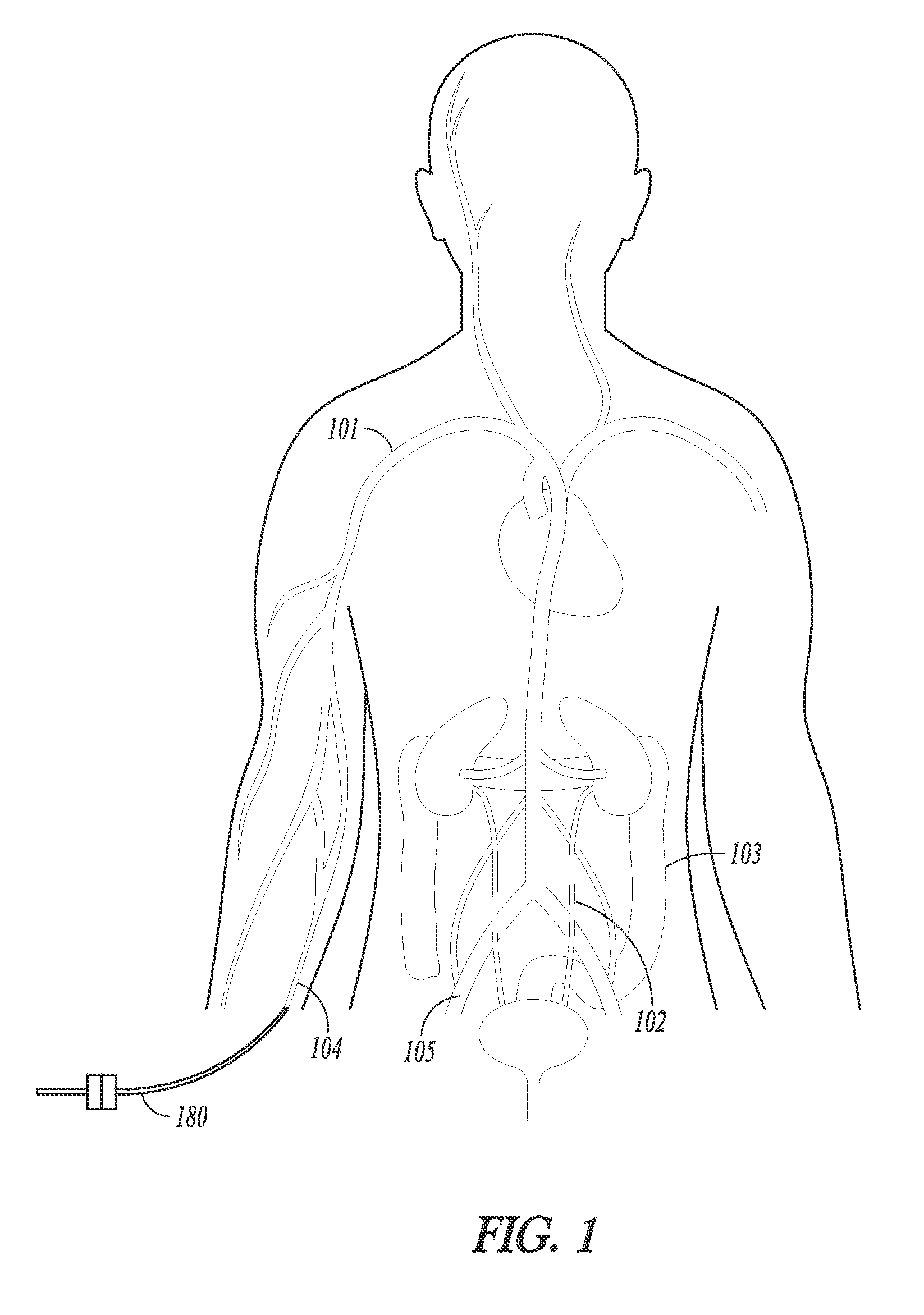
[0057]The present inventors recognize, among other things, a need for gaining access into a body vessel or body cavity of a patient, such as a radial or femoral artery, while protecting vessel or cavity walls and preserving vessel or cavity access size (e.g., effective vessel diameter or cross-sectional area). Using this larger-than-conventional access size, caregiver-selected treatment devices can be efficiently introduced into a desired body vessel or body cavity during a minimally invasive procedure.

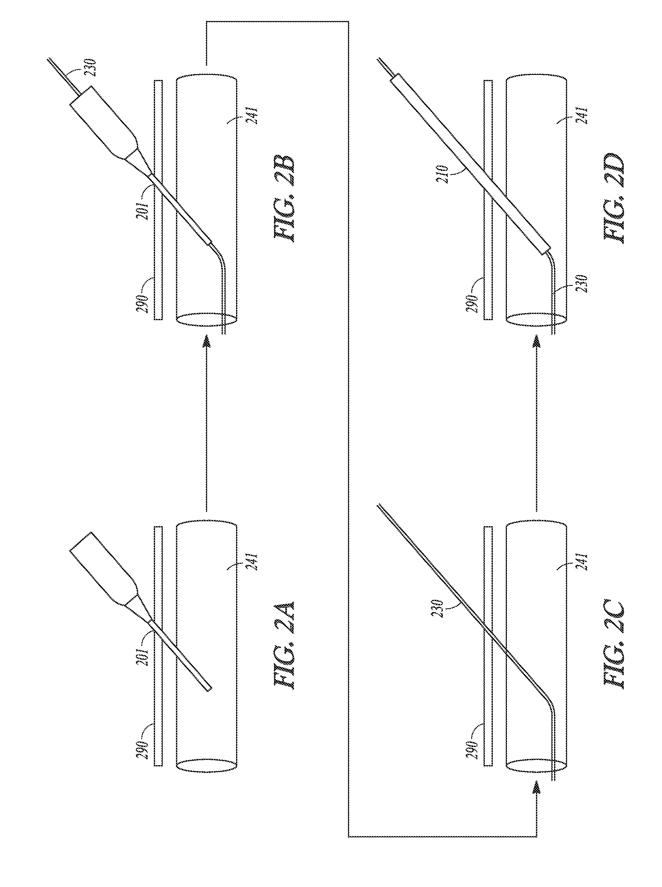
[0058]The present vascular dilator systems, kits, and methods comprise or use a dilator assembly including a tubular shaft and a deformable member. Together, the tubular shaft and the deformable member can allow for sheathless introduction of a treatment device into a body vessel or body cavity in a safer and less painful manner than is currently possible. The tubular shaft can have an outer surface that gradually increases in diameter between a shaft distal end portion and a shaft pr...


PUM


Abstract

Vascular dilator systems, kits, and methods allowing for sheathless introduction of a treatment device into a body vessel or body cavity are disclosed. A vascular dilator system can include a dilator assembly, including a tubular shaft and a deformable member, and optionally, the treatment device. The deformable member can include a non-biodegradable material and can have a diameter at a proximal end portion that is greater than a diameter at a distal end portion. The distal end portion of the deformable member can be coupled to an outer surface of the tubular shaft, at or near a shaft distal end portion. The proximal end portion of the deformable member can include a diameter configured to receive or stretch around a distal end portion of the treatment device. In use, the deformable member can provide a tapered bridge between the outer surface of the tubular shaft and an outer surface of the treatment device.

Description

TECHNICAL FIELD[0001]This patent document pertains generally to systems, kits, and methods to introduce a treatment device into a body vessel or body cavity. More particularly, but not by way of limitation, this patent document pertains to vascular dilator systems, kits, and methods configured to protect body vessel or body cavity wall surfaces, while preserving vessel or cavity access size.BACKGROUND[0002]Minimally invasive procedures have been implemented in a variety of medical settings, such as for vascular interventions, stenting, embolic protection, electrical heart stimulation, heart mapping and visualization, and the like. These procedures generally rely on accurately navigating and placing treatment devices within a body vessel or body cavity.[0003]During minimally invasive procedures, a body vessel, for example, can be accessed through a small access hole. The small access hole can be initiated by piercing the skin, the body vessel, and any intermediate structures using a ...

Claims


Application Information

Patent Timeline
Patent Type & Authority Applications(United States)
IPC IPC(8): A61M29/00
CPCA61M29/00A61M25/0662A61M2025/0681
Inventor ROOT, HOWARDHOLMAN, THOMASFRASER, DOUGDEEPA, DEEPA
Owner TELEFLEX LIFE SCI LTD
Learn More