Socket insert adapter and method of use

a socket insert and adapter technology, applied in the field of socket inserts, can solve the problems of not offering grip to operate on different shapes and sizes of fasteners, spinning and slippage, and the socket driver is not efficient in preventing the rotation of nuts/bolts, etc., to achieve the effect of maximizing torque and maximizing torqu

Active Publication Date: 2014-09-11
TAYLOR JR JAMES W
View PDF12 Cites 8 Cited by
  • Summary
  • Abstract
  • Description
  • Claims
  • Application Information

AI Technical Summary

Benefits of technology

[0010]Another objective of the present invention is to provide unique design inserts with rounded outside corners and rounded inside corners to maximize the torque on the flat wall of the insert.
[0014]A further objective of the present invention is to provide an efficient, light weight, compact adjustable socket insert for socket drivers.
[0015]Yet another objective of the present invention is to provide a socket insert which can operate on interchangeable metric or SAE sizes using the same socket driver.
[0018]Some embodiments of the hollow shaped socket insert adapters are provided with rounded outside corners to avoid contacting inner corners of a socket driver and to maximize torque between outer walls of the adapter and inner walls of the socket driver. Some embodiments of the hollow shaped socket insert adapters are provided with rounded inner corners to avoid contact with corners of a nut / bolt to be driven and to maximize torque between inner walls of adapter and outer walls of the nut / bolt to be driven.
[0019]The hollow shaped socket insert adapter specific to the size of the subject nut / bolt to be driven is chosen and placed inside the socket driver cavity. Force is applied to the socket driver body enabling the hollow shape socket insert adapter to tighten, loosen, and remove the subject nut / bolt.
[0020]In some embodiments, a mechanical arrangement for electrically, hydraulically, or pneumatically tightening, loosening or removing nuts and bolts of various sizes is provided. The mechanical arrangement includes a socket driver configured to receive and to be rotatively driven by a torque force from at least one of electrical, hydraulic, or pneumatic means, wherein the torque force generated by the electrical, hydraulic or pneumatic means is greater than a torque force that can be applied manually by a human being; a plurality of hollow-shaped socket insert adapters that are configured to be rotatively driven by a the socket driver, and to receive the electrical, hydraulic, or pneumatic torque force via the socket driver, for tightening, loosening, or removing the nuts and bolts of various sizes, a given one hollow-shaped socket insert adapter of the plurality of hollow-shaped socket insert adapters. The hollow-shaped socket insert adapters include an inner configuration that has a shape and size to conform to and to fit on a head portion, having outside corners, of a given nut or bolt to be driven and wherein the shape of the inner configuration is a closed hollow shape. The mechanical arrangement also includes one or more inner flat walls and one or more rounded inner corners, the inner configuration being shaped to allow the one or more flat walls of the inner configuration to contact and engage, and the one or more rounded inner corners to avoid contacting and engaging, the outside corners of the head portion of the given nut or bolt to be driven; and the flat walls and rounded outer and inner corners increase the ability of the plurality of hollow-shaped socket insert adapters to receive the electrical, hydraulic, or pneumatic torque force via the socket driver and to transmit the torque force to the given nut or bolt to be driven.

Problems solved by technology

Some adjustable socket drivers having a movable jaw and a fixed jaw are available in the prior art to engage nuts / bolts of various dimensions and shapes but such socket drivers are not efficient to prevent rotation of nuts / bolts and do not offer grip to operate on different shapes and sizes of fasteners.
One of the common problem with inserts used in socket drivers of the prior art is the sharp corners which cause the spinning and slippage while providing torque to the inserts because of the improper locking between the insert and socket driver.
The major drawback with existing split side, gap wall, and similar inserts available in the prior art is that they fail to provide the durability, strength, and efficiency for driving large diameter of nuts / bolts.

Method used


Image

  • Socket insert adapter and method of use
  • Socket insert adapter and method of use
  • Socket insert adapter and method of use

Examples


Embodiment Construction

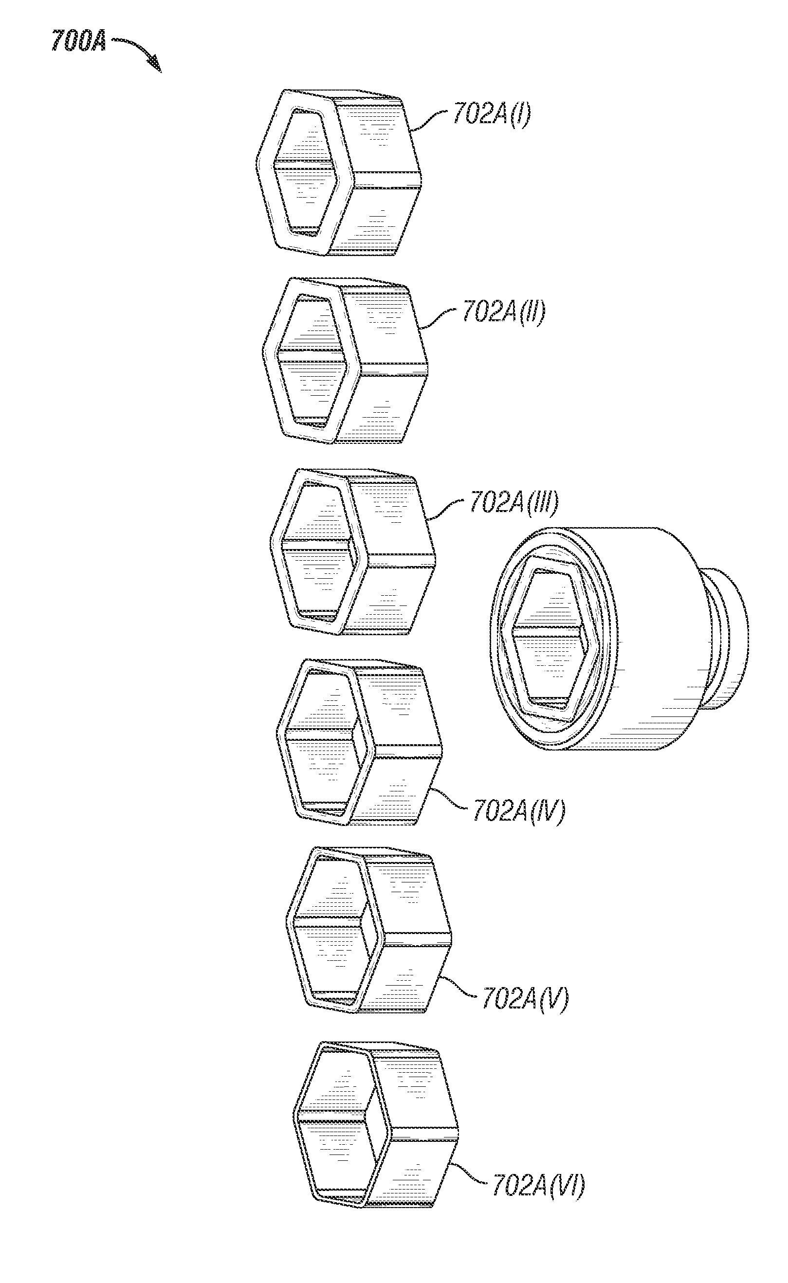
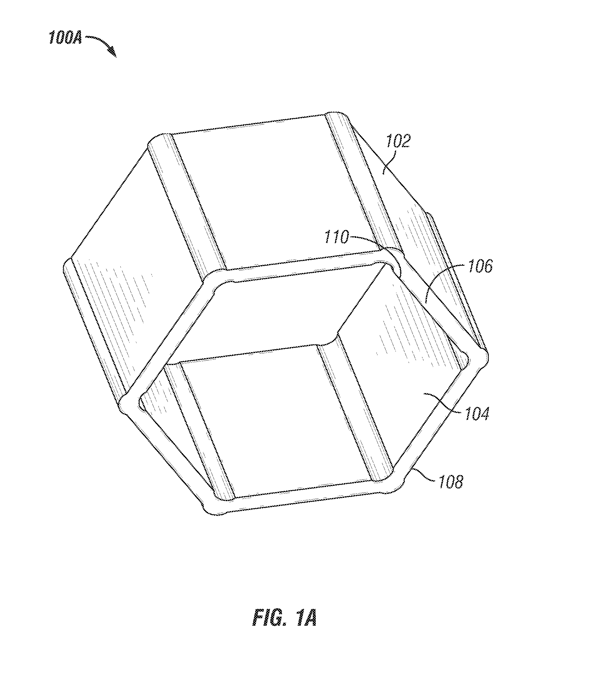
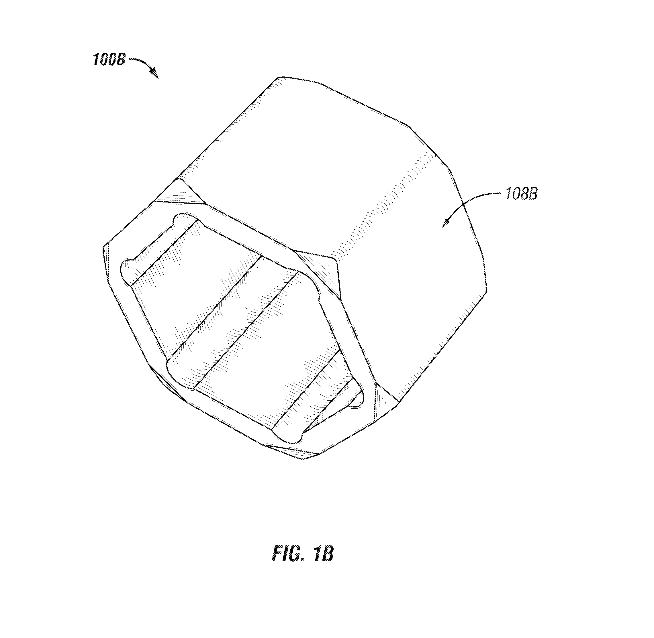
[0053]Embodiments of the present invention provide a socket insert for tightening, loosening, and removing various nuts / bolts of smaller dimensions used in conjunction with a single socket driver. The following detailed description is merely exemplary in nature and is not intended to limit the described embodiments or the application and uses of the described embodiments. As used herein, the word “exemplary” or “illustrative” means “serving as an example, instance, or illustration.” Any implementation described herein as “exemplary” or “illustrative” is not necessarily to be construed as preferred or advantageous over other implementations. All of the implementations described below are exemplary implementations provided to enable persons skilled in the art to practice the disclosure and are not intended to limit the scope of the claims. Furthermore, there is no intention to be bound by any expressed or implied theory presented in the preceding technical field, background, brief sum...


PUM


Abstract

A hollow shaped socket insert adapter rotatively driven by a single socket driver for tightening, loosing, and removing various sizes of nuts / bolts.

Description

CROSS REFERENCE TO RELATED APPLICATIONS[0001]This application is a continuation application of U.S. Ser. No. 13 / 283,499, filed Oct. 27, 2011, entitled “Socket Insert Adapter and Method of Use”, which is a continuation-in-part application of U.S. Ser. No. 12 / 434,609, entitled “Socket Insert Adapter”, filed May 1, 2009, both applications incorporated herein for all purposes.DESCRIPTION[0002]1. Field of the Invention[0003]The present invention in general relates to a socket insert. More particularly, it relates to a hollow shape socket insert adapter used in conjunction with a socket driver for tightening, loosening, removing various sizes of nuts and bolts.[0004]2. Background of the Invention[0005]Sockets are one of the most commonly used mechanical tools for driving nuts and bolts. Most of the earlier standard socket drivers were designed with specific metric or SAE size for fastening nuts / bolts thus each time a different socket driver was required for driving nuts / bolts of various d...

Claims


Application Information

Patent Timeline
Patent Type & Authority Applications(United States)
IPC IPC(8): B25B13/58B25B13/06
CPCB25B13/06B25B13/58B25B13/065B25B13/107B25B13/56
Inventor TAYLOR, JR., JAMES W.
Owner TAYLOR JR JAMES W
Why Eureka
Try Eureka