Inflatable hull and buoyant vehicle, in particular a dinghy

a technology which is applied in the field of inflatable hull and buoyant vehicle, can solve the problems of limited rigidity of inflatable hull, and inability to support the weight of one or more crew members, and achieves the effect of heavy weight and simple manufacturing

Active Publication Date: 2014-09-11
SAS TIWAL
View PDF3 Cites 8 Cited by
  • Summary
  • Abstract
  • Description
  • Claims
  • Application Information

AI Technical Summary

Benefits of technology

[0008]The invention has other purposes than proposing an inflatable hull that remedies the above-stated disadvantages, namely an inflatable hull that is rigid during navigation, without requiring a structure, capable of carrying heavy weight and of withstanding big stresses, that can have a bottom of the desired form, and that is simple to manufacture.
[0009]For this purpose, the invention addresses an inflatable hull incorporating at least one pneumatic envelope with two superimposed walls, each of which aforesaid walls has a textile layer and is interconnected by a multitude of joining threads distributed over the entire surface of the said layers, forming a structure that is suitable for being inflated to a pressure that can instill rigidity in the said structure, and that ensures the buoyancy of the said hull, independently of any added buoyancy component, with this hull being remarkable in the fact that the said envelope has an initial curvature in the transversal cross-section and a second curvature over at least its front part in the longitudinal cross-section, with one of the said walls being positioned on the interior side of the said curvature, with the other of the said walls being on the exterior side of the said curvature, and with the said envelope having at least one tuck designed to form a bow.
[0011]The use of a restricted number of pieces for the manufacturing of the inflatable hull, and the general structure of it is such that the pneumatic envelope plays both the role of a buoyancy chamber, deck and seating. The result is that the inflatable hull is lighter, and that the manufacture, maintenance and repairing of it are greatly facilitated. The tuck constitutes a particularly simple means of producing the bow, in an area in which the hull has both a curvature in the transversal cross-section and a curvature of longitudinal cross-section.
[0019]Thus manufactured, the inflatable hull according to the invention has good hydrodynamic performances and a high-quality behavior during navigation. The shape endowed upon the lateral strip and the transversal strip, that the dual-wall envelope is constrained to marry its inflated state, constitutes a particularly simple means of endowing respectively the longitudinal cross-section and the transversal cross-section of the hull with the desired non-flat profile.
[0020]According to another possible characteristic of the invention, the hull includes at least one impermeable interior strip positioned in a median longitudinal plane between the said walls, to impermeably partition the said pneumatic envelope into an inflatable and deflatable starboard part and port part, that are inflatable and deflatable independently of each other. This is a simple means of producing two independent compartments in the envelope. This way, one conserves a safety buoyancy in the event of an air leak.
[0032]According to another possible characteristic of the invention, the said vessel includes wings designed to be fixed on each side of the floating vessel, on one of the said branches for the rudder mounting, and on one exterior extremity of the said bearing parts, with the said wings forming—with the said branches and the said bearing parts—a closed structure endowing rigidity on each side of the said hull. This structural ensemble contributes to further rigidifying the hull.

Problems solved by technology

The first disadvantage of these floating vessels that is known is due to the fact that the rigidity of their inflatable hull is lesser than that of a known floating vessel with a hull in a hard material.
Consequently, their ability to support the weight of one or more crew members, and their ability to withstand the stresses applied by water and by the mast on the inflatable hull are limited or require the addition of bulky rigid structural reinforcements.
A second disadvantage of these known floating vessels is the shape of the bottom of their inflatable hull, which is flat.
Consequently, their inflatable hull has lesser hydrodynamic performances and their behavior under navigation is of lesser quality than that of a known hull that has a bottom of non-flat transversal cross-section—for example, with a U-shaped or V-shaped general form, together with a non-flat longitudinal cross-section and a bow.
A third disadvantage of these known floating vessels is the complexity of assembly of the various pneumatic envelopes of which their inflatable hull is composed.
Consequently, the time needed for their production, maintenance and any necessary repairs is long, and this has an unfavorable repercussion on the production costs.
In addition, the complexity requires a consequential usage of materials, so these inflatable hulls have a relatively heavy weight.
These disadvantages notably also apply to other forms of inflatable hulls covered in the patents JP2007176236, FR2722758 and US2011036284, which have a complex structure incorporating a peripheral buoyancy pudding fender, as well as a deck and transom.
Also, the latter are mainly intended for motor propulsion, and do not have good nautical qualities when they are sail-powered because, in addition to being relatively heavy, they do not have a good water contact
A fourth disadvantage of these known floating vessels is the lack of structural rigidity of the assembly between the inflatable hull and the equipment of centerboarder type, which does not enable one to use a sail of comparable power to that on a centerboarder constructed in hard material.
Consequently, their performance under navigation is lesser than that of known centerboarders constructed with a hull in hard material.
However, the hull of the vessel according to document US 2009 / 0031941 has a relatively-complex conventional structure, which is prejudicial, notably from the viewpoint of production cost, weight, ease of use and reliability.
Supposing that such a dual-wall envelope with joining threads of variable lengths is implementable, it would be a complex way of endowing a desired form on the inflatable compartments.

Method used


Image

  • Inflatable hull and buoyant vehicle, in particular a dinghy
  • Inflatable hull and buoyant vehicle, in particular a dinghy
  • Inflatable hull and buoyant vehicle, in particular a dinghy

Examples


Embodiment Construction

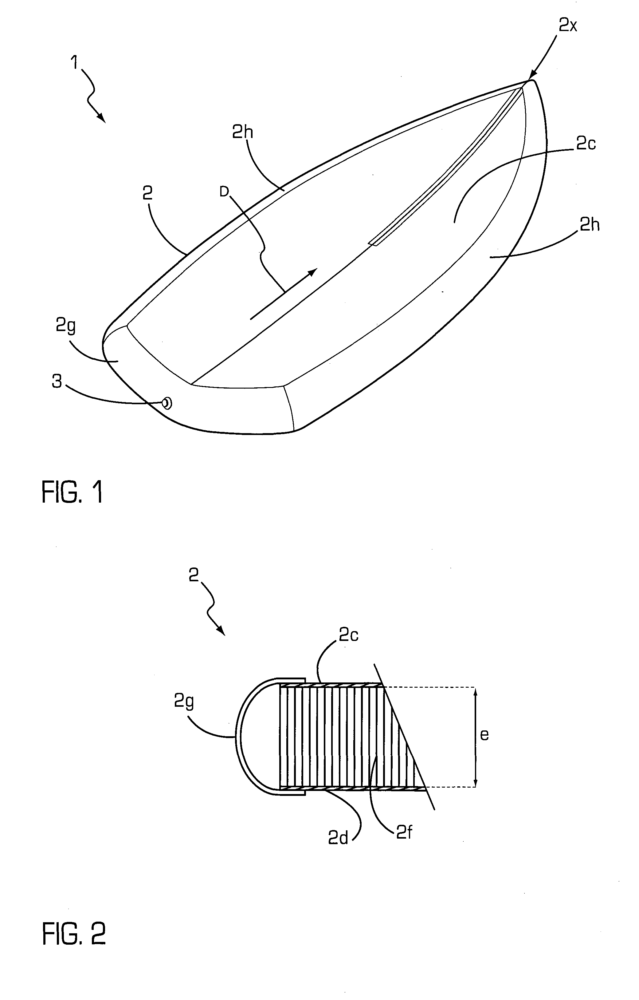
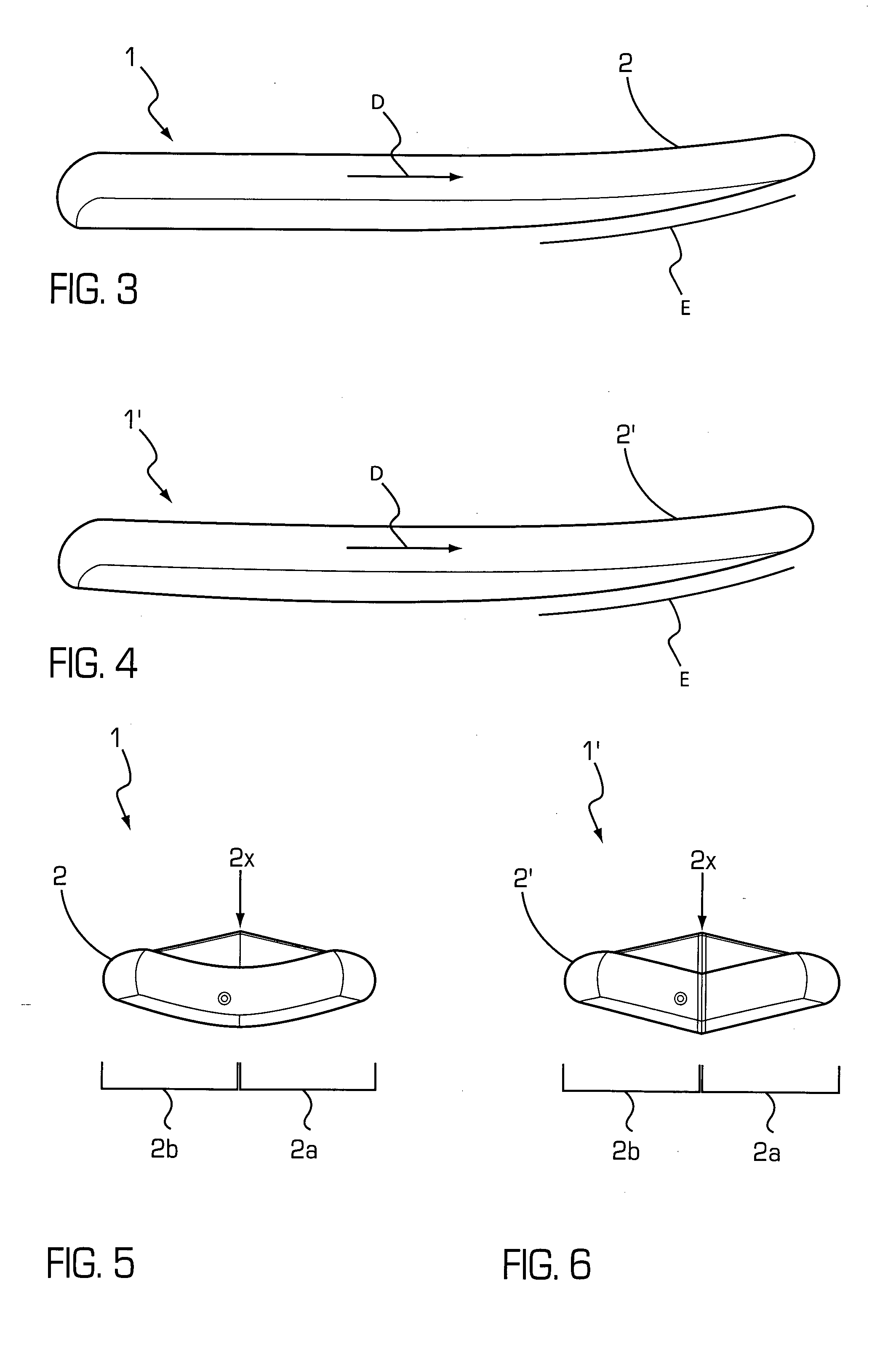
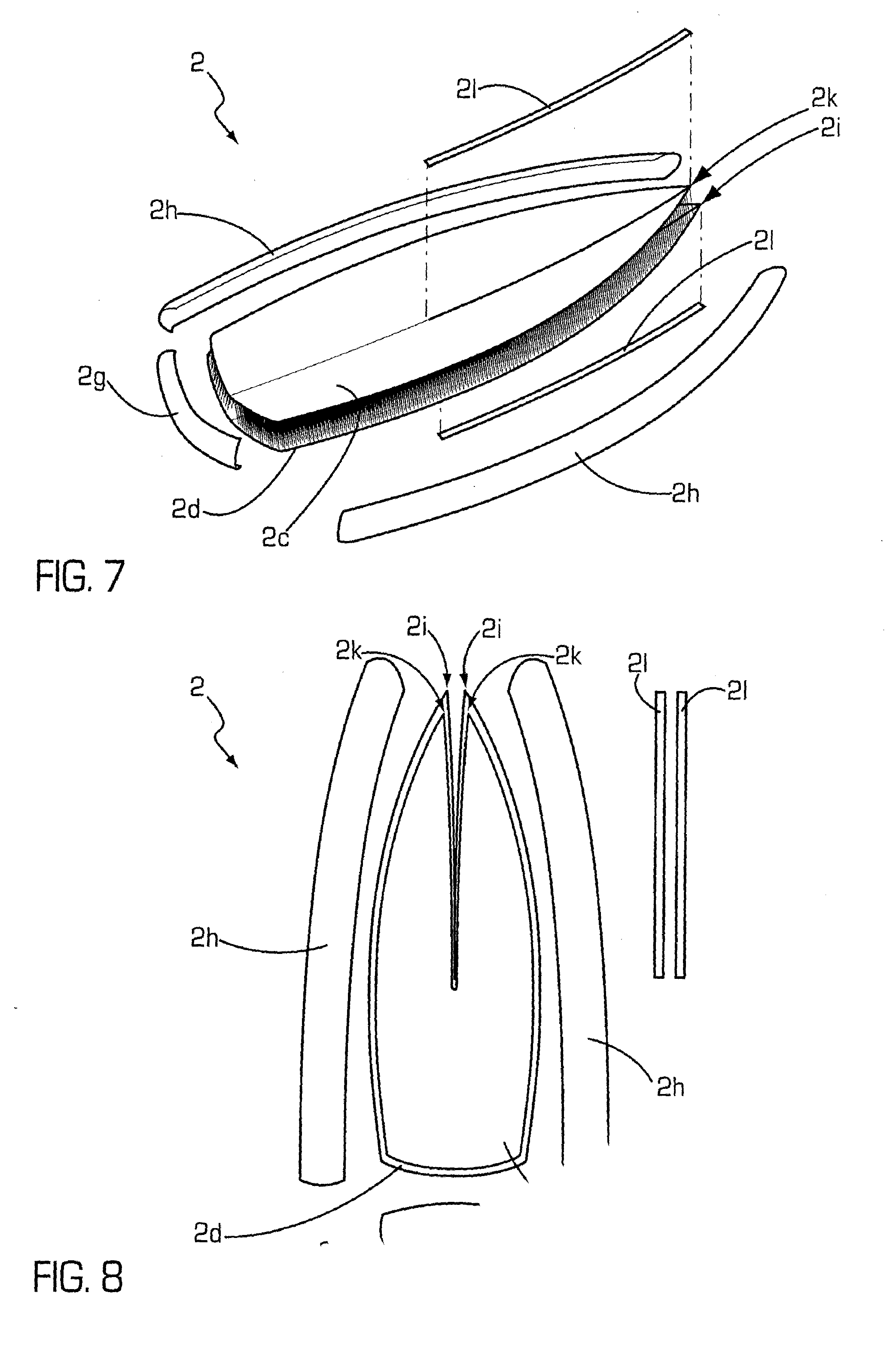
[0056]If one refers to FIG. 1, in a preferred form of implementation, the inflatable hull (1) is composed of at least one pneumatic envelope (2) and is advantageously equipped with an inflation and deflation valve (3). The inflatable hull is designed to be rolled or folded. It is light and has very small outside dimensions, which facilitates its storage, handling and transportation.

[0057]In use, the inflatable hull (1) withstands the forces applied by water on its submersed parts, the stresses applied by the propulsion system fixed on the inflatable hull (1), and the weight of one or more people. It is therefore essential that the inflatable hull (1) be rigid during navigation. To achieve this end, the pneumatic envelope (2) of the inflatable hull (1) is made of dual-wall textile, as can be more clearly seen in FIG. 2. Dual-wall textiles are known, moreover, and their production process will not be described herein. If one refers to FIG. 2, the dual-wall textile takes the form of tw...


PUM


Abstract

An inflatable hull including at least one air casing that has two walls placed one over the other. The walls each include a fabric sheet, are connected therebetween by a plurality of connecting wires distributed over the entire surface of the sheets while forming a structure suitable for being inflated to a pressure capable of rigidifying the structure, and are capable of ensuring the buoyancy of the hull separately from any reported buoyancy element. The casing has a first transversely cross-sectional curvature and a second longitudinally cross-sectional curvature that is present over at least the front portion of the casing. One of the walls corresponds to the inside of the curvature, and the other of the walls corresponds to the outside of the curvature. The casing has at least one clip set up such as to form a stem.

Description

FIELD OF THE INVENTION[0001]The invention herein concerns an inflatable hull that is particularly—but not exclusively—intended for sail power, and a floating vessel—notably of centerboarder type—incorporating such an inflatable hull.BACKGROUND OF THE INVENTION[0002]There are, at present, floating vessels that incorporate an inflatable hull and that can be mainly equipped with a rudder, a centerboard well, a centerboard, a mast foundation base, a mast, and a sail. Patents U.S. Pat. No. 3,577,576, DE29919234, U.S. Pat. No. 4,149,481, U.S. Pat. No. 4,750,446, WO8606388 and DE3004416 are testimony to prior state of the art in the domain concerned.[0003]The first disadvantage of these floating vessels that is known is due to the fact that the rigidity of their inflatable hull is lesser than that of a known floating vessel with a hull in a hard material. Consequently, their ability to support the weight of one or more crew members, and their ability to withstand the stresses applied by wa...

Claims


Application Information

Patent Timeline
Patent Type & Authority Applications(United States)
IPC IPC(8): B63B7/08B63B15/02
CPCB63B15/02B63B7/082B63B3/18B63B2035/009B63B7/08
Inventor EXCOFFON, MARION
Owner SAS TIWAL
Why Eureka
Try Eureka