Fuel Injection Valve

a fuel injection valve and valve body technology, applied in the direction of fuel injection apparatus, combustion engines, charge feed systems, etc., can solve the problems of affecting the accuracy of fuel injection characteristics, deteriorating accuracy, and affecting the substantial symmetry (high circumferential uniformity) so as to increase the uniformity of swirling fuel flow

Active Publication Date: 2014-09-11
HITACHI ASTEMO LTD
View PDF11 Cites 0 Cited by
  • Summary
  • Abstract
  • Description
  • Claims
  • Application Information

AI Technical Summary

Benefits of technology

[0012]According to the present invention, the circumferential uniformity of each swirling fuel flow is increased, forming fuel like a thin film is promoted, and the fuel is finely atomized.

Problems solved by technology

Particularly, the total volume of fuel flow paths affects the accuracy of fuel injection characteristics (the accuracy deteriorates when the total volume is large).
When such an uneven flow of fuel enters each swirling chamber without being adequately rectified, part of the fuel is caused to rapidly flow toward the associated fuel injection orifice, possibly impairing the substantial symmetry (high circumferential uniformity) of the swirling fuel flow.

Method used


Image

  • Fuel Injection Valve
  • Fuel Injection Valve
  • Fuel Injection Valve

Examples


Embodiment Construction

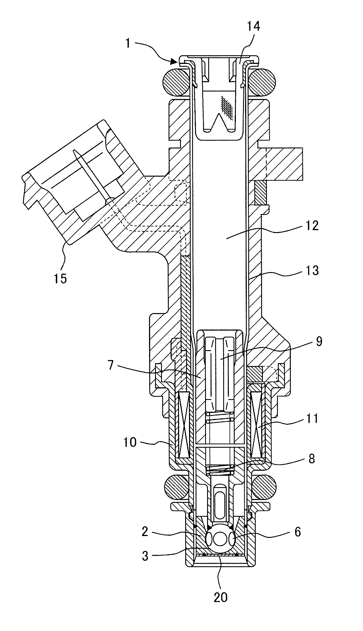
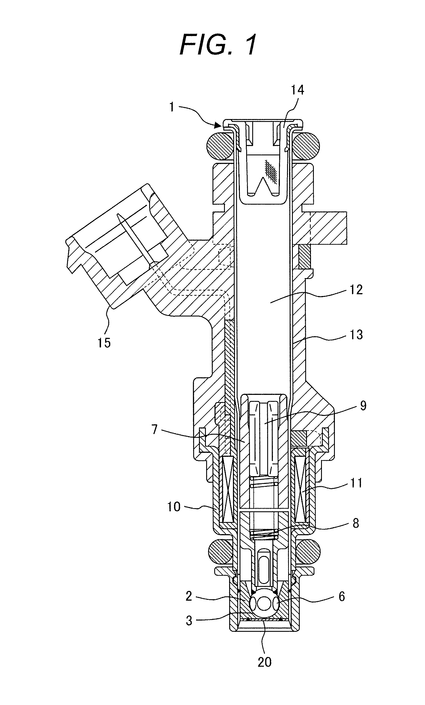
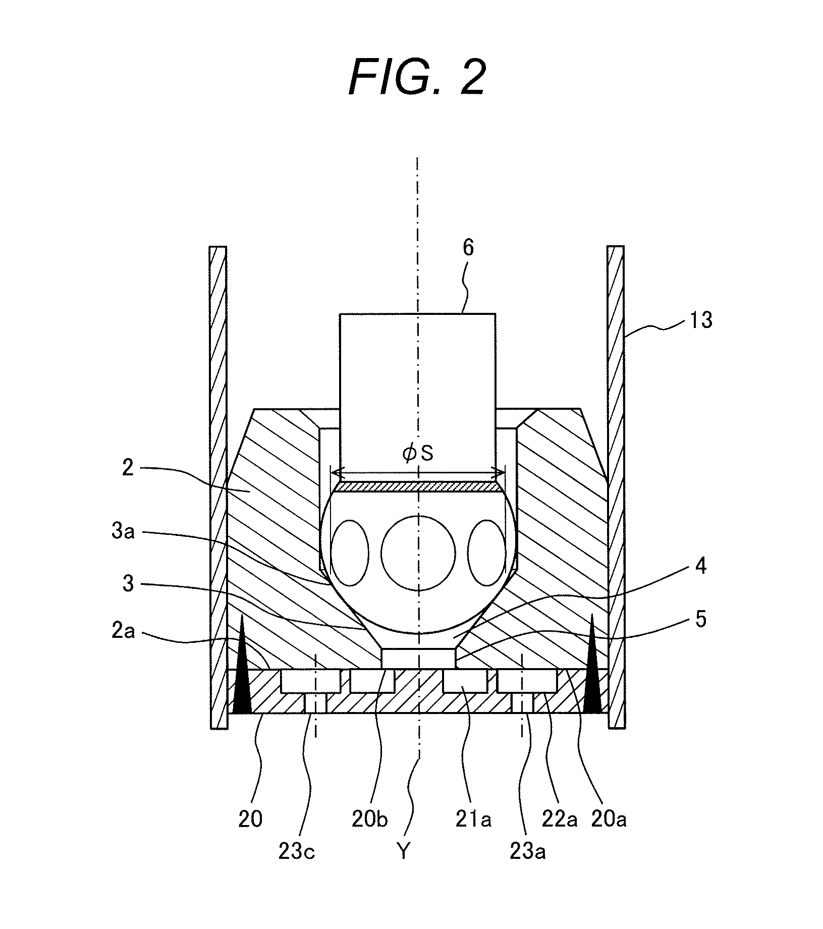
[0028]An embodiment of the present invention will be described below with reference to FIGS. 1 to 6. FIG. 1 is a longitudinal sectional view taken along the valve axis of a fuel injection valve 1 according to an embodiment of the present invention and represents an overall structure of the valve.

[0029]Referring to FIG. 1, in the fuel injection valve 1, a thin-walled, stainless-steel pipe 13 accommodates a nozzle body 2 and a valve element 6, and the valve element 6 is reciprocally moved (for opening / closing operation) by an electromagnetic coil 11 disposed outside the valve element 6. In the following, the structure of the fuel injection valve 1 will be described in detail.

[0030]The fuel injection valve 1 includes a magnetic yoke 10 surrounding the electromagnetic coil 11, a core 7 centrally positioned in the electromagnetic coil 11 with one end thereof magnetically connected to the yoke 10, a valve element 6 which can be lifted by a predetermined distance, a valve seat surface 3 wh...


PUM


Abstract

A fuel injection valve realizing improved circumferential uniformity of swirling fuel is provided. The fuel injection valve includes a swirling chamber having an inner peripheral wall whose curvature is gradually larger from upstream to downstream, a path for swirling which, having a fuel flow-in region formed along a valve axis direction, guides fuel to the swirling chamber, and a fuel injection orifice open into the swirling chamber. In the fuel injection valve, the path for swirling is inclined toward the fuel injection orifice formed on a downstream side of the swirling chamber.

Description

CLAIM OF PRIORITY[0001]The present application claims priority from Japanese application serial no. 2013-046088, filed on Mar. 8, 2013, the content of which is hereby incorporated by reference into this application.FIELD OF THE INVENTION[0002]The present invention relates to a fuel injection valve for use in an internal combustion engine and, more particularly, to a fuel injection valve capable of spraying swirling fuel to improve fuel atomization performance.BACKGROUND OF THE INVENTION[0003]An example of fuel injection valve using a known technique is disclosed in Japanese Unexamined Patent Publication No. 2003-336562. In the technique, atomization of fuel injected from plural fuel injection orifices is promoted making use of a swirling fuel flow.[0004]The fuel injection valve has a valve seat member in which a downstream end of a valve seat cooperating with a valve element has opening formed through the front end surface of the valve seat member and an injector plate joined to the...

Claims


Application Information

Patent Timeline
Patent Type & Authority Applications(United States)
IPC IPC(8): F02M63/00
CPCF02M63/0078F02M61/184F02M61/163F02M61/1853
Inventor OKAMOTO, YOSHIOYOSHIMURA, KAZUKIMAEKAWA, NORIYUKIKOBAYASHI, NOBUAKIISHII, EIJISAITO, TAKAHIRO
Owner HITACHI ASTEMO LTD
Why Eureka
Try Eureka