Inner-Diameter Quenching Device

Active Publication Date: 2014-09-11
HIWIN TECH
View PDF2 Cites 5 Cited by
  • Summary
  • Abstract
  • Description
  • Claims
  • Application Information

AI Technical Summary

Benefits of technology

[0012]The heating coil and the spray cylinder are separated and movable in opposite directions along the same center axis, which can further reduce the size of the quenching device of the present inventi

Problems solved by technology

This conventional quenching device 10 is capable of heating and cooling, however, the heating coil 11 and the cooling liquid output device 12 have the same moving path, so that the arrangement of circuit line and pipeline is difficult and complic

Method used


Image

  • Inner-Diameter Quenching Device
  • Inner-Diameter Quenching Device
  • Inner-Diameter Quenching Device

Examples


Embodiment Construction

[0025]The present invention will be clearer from the following description when viewed together with the accompanying drawings, which show, for purpose of illustrations only, the preferred embodiment in accordance with the present invention.

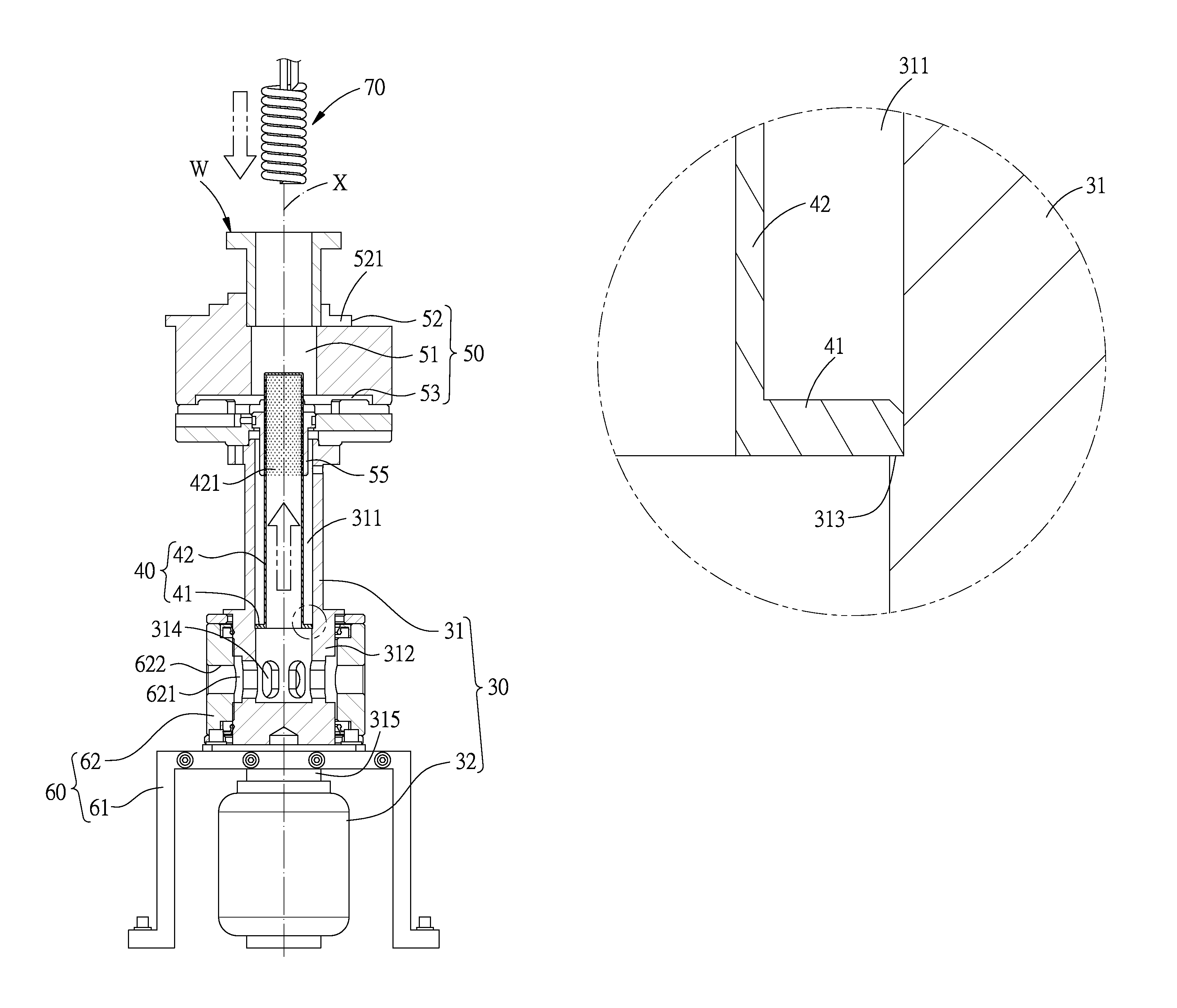
[0026]Referring to FIGS. 3-6, an inner-diameter quenching device in accordance with a first embodiment of the present invention is provided with a workpiece holding assembly 50 to hold a workpiece W to be quenched, and a heating coil 70 and a spray cylinder 40 move in the inner diameter of the workpiece W to be quenched. The workpiece W to be quenched has a central axis X, and the heating coil 70 and the spray cylinder 40 move in opposite directions along the central axis X. A rotation assembly 30 drives the workpiece holding assembly 50 to rotate about the central axis X, and a lifting assembly 60 drives the spray cylinder 40 to move upward along the central axis X.

[0027]The rotation assembly 30 includes a shaft 31 and a motor 32. The shaft 31 i...


PUM

PropertyMeasurementUnit
Angleaaaaaaaaaa
Diameteraaaaaaaaaa

Abstract

An inner-diameter quenching device is provided with a workpiece holding assembly for holding a workpiece to be quenched, a spray cylinder, and a heating coil. The workpiece has a central axis. The spray cylinder is disposed at a first side of the workpiece holding assembly and driven by a lifting assembly to move along the central axis into an inner diameter of the workpiece. The heating coil is disposed at a second side of the workpiece holding assembly and located on and movable along the central axis. The heating coil and the spray cylinder are separated and movable in opposite directions along the same center axis, which can further reduce the size of the quenching device, making it suitable for quenching a small inner-diameter workpiece. Besides, the spray apertures are inclined, so that the cooling liquid can be sprayed out more easily to enhance the quenching effect.

Description

BACKGROUND OF THE INVENTION[0001]1. Field of the Invention[0002]The present invention relates to a hot processing device, and more particularly to an inner-diameter quenching device.[0003]2. Description of the Prior Art[0004]Quenching is the rapid cooling of a metal material to obtain certain material properties. FIG. 1 shows a conventional quenching device 10 which is provided with a heating coil 11 and a cooling liquid output device 12, wherein the quenching device 10 moves in a workpiece to be quenched, so that the workpiece can be heated by the heating coil 11 and cooled down by the cooling liquid output device 12 at the same time. This conventional quenching device 10 is capable of heating and cooling, however, the heating coil 11 and the cooling liquid output device 12 have the same moving path, so that the arrangement of circuit line and pipeline is difficult and complicated, thus resulting in large size and complicated structure of the quenching device 10.[0005]FIG. 2 shows ...

Claims


Application Information

Patent Timeline
IPC IPC(8): C21D1/667
CPCC21D1/667
Inventor CHANG, SHIH-TIENCHI, KUN-HUNG
Owner HIWIN TECH
Why Eureka
Try Eureka