
Retractable Cord Queue Barrier System

a barrier system and retractable cord technology, applied in the direction of doors/windows, curtain suspension devices, doors, etc., can solve the problems of inability to maintain the constant refraction force of the spring, the inability to balance between, and the inability to deploy retractable belts or tape restraints between the stanchions

Active Publication Date: 2014-09-11
10-31 INC
View PDF9 Cites 4 Cited by
  • Summary
  • Abstract
  • Description
  • Claims
  • Application Information

AI Technical Summary

Benefits of technology

The present invention solves the problem of a spring-loaded spool retraction mechanism causing abrupt snap-back of the extended cord and excessive pulling force on the cord, which tends to cause the stanchion to tip over. Instead, a spring-biased pulley retraction mechanism is used with a constant-force coiled metal spring that does not increase the retraction force as the cord is extended. The use of a cord with a stretch factor of less than 50% achieves a dynamic balance between the contraction force of the cord and the constant retraction force of the spring-biased pulley system. This allows the tension of the cord to be maintained without exerting an excessive tipping force on the stanchion.

Problems solved by technology

For that reason, barriers that deploy retractable belt or tape restraints between the stanchions are not desirable, because the breadth of the belt or tape interferes with the patrons' view of the protected object.
In combination with a constant-force spring, on the other hand, a balance between the proportionally increasing contraction force of 100% stretch cord and the constant refraction force of the spring cannot be maintained over the entire extension of the cord.
Either the spring must be over-sized, in which case the extended cord will be excessively taut, creating a tripping / safety hazard, or the spring must be under-sized, in which case the extended cord will be slack and unsightly and will not retract properly.

Method used


Image

  • Retractable Cord Queue Barrier System
  • Retractable Cord Queue Barrier System
  • Retractable Cord Queue Barrier System

Examples


Embodiment Construction

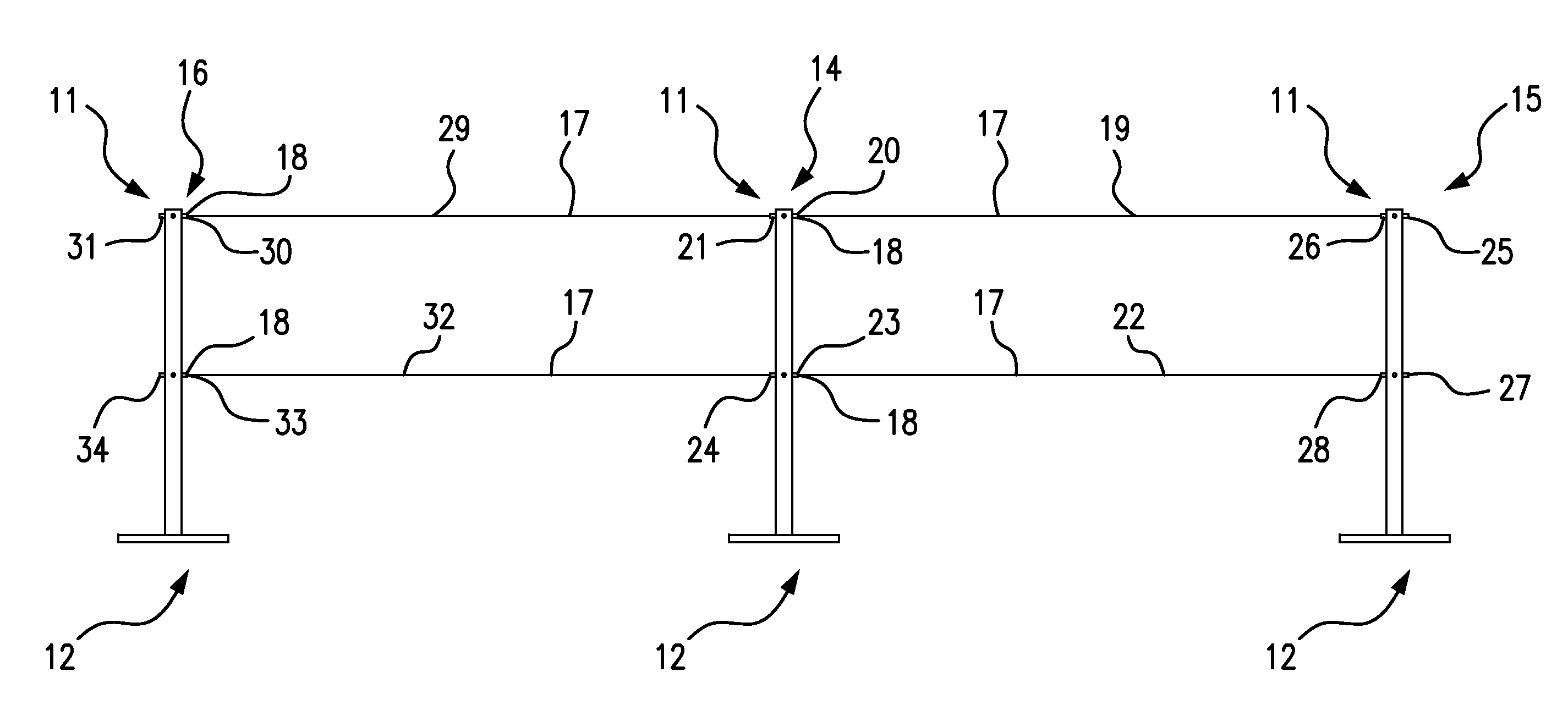
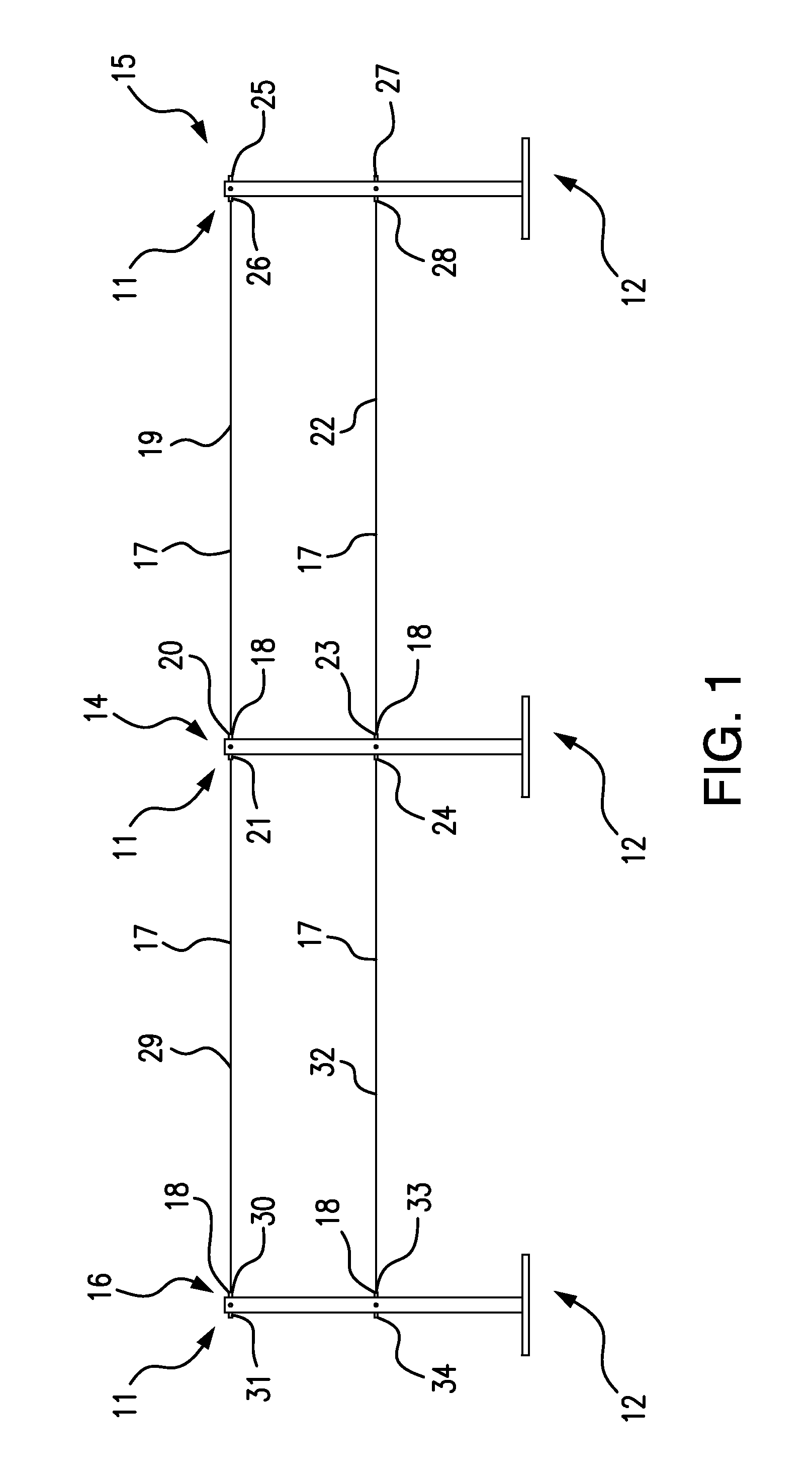
[0028]Referring to FIG. 1, an exemplary queue barrier system 10 according to the present invention comprises three (3) tubular stanchions 11, each supported by a weighted base 12. Alternately, each of the stanchions can be anchored in a floor socket 13, of which FIGS. 7A-7D depict an illustrative example.

[0029]In FIG. 1, a first stanchion 14 is releasably connected to a second stanchion 15 by two retractable elastic cords 17, which extend from two cord apertures 18 in the first stanchion 14. A first upper cord 19 extends from a first upper cord aperture 20 of the first stanchion 14 and releasably attaches to a second upper cord connector 26 of the second stanchion 15. A first lower cord 22 extends from a first lower cord aperture 23 of the first stanchion 14 and releasably attaches to a second lower cord connector 28 of the second stanchion 15.

[0030]The reason for having both upper and lower cords 17 interconnecting the stanchions 11 is compliance with ADA requirements, with the low...


PUM


Abstract

A retractable cord queue barrier system uses a spring-biased pulley refraction mechanism acting on a stretchable cord. A constant-force coiled metal spring is used, such that the retraction force on the cord does not increase as the cord is extended—as it would for a helical spring governed by Hooke's Law. The use of a constant-force spring avoids abrupt snap-back of the extended cord when released, as well as the need for excessive pulling force on the cord as it approaches full extension, which tends to cause the stanchion to tip over. Dynamic balance between the contractive force of the stretchable cord and the retractive force of the constant-force spring achieves a taut but not unyielding tension in the interconnecting cords between stanchions.

Description

BACKGROUND OF THE INVENTION[0001]The present invention relates to the general field of pedestrian barriers, and more particularly to the field of barriers used to control and direct groups of people in public places.[0002]Queue barriers are commonly used to guide and control crowds of people at public events and exhibits. Typical freestanding queue barriers comprise a draped rope or retractable belt stretched between upright tubular stanchions, each mounted on a weighted circular base. For aesthetic reasons, it is often desirable to minimize the diameter of the stanchions and the bulk of the base. The preference for a sleek, unobtrusive look, particularly at artistic exhibits, can dictate the use of slender cords rather than belts between the stanchions.[0003]While spring-loaded spool mechanisms are suitable for use with retractable belt barriers, a spool for the equivalent length of cord would need to be much wider—requiring an unsightly larger stanchion diameter. For retractable c...

Claims


Application Information

Patent Timeline
IPC IPC(8): E01F13/02
CPCE01F13/028
Inventor STENDER, WILLIAMSTENDER, EVAN
Owner 10-31 INC
Learn More