Actuator control method and actuator control device

Active Publication Date: 2014-09-11
ISUZU MOTORS LTD
View PDF3 Cites 2 Cited by
  • Summary
  • Abstract
  • Description
  • Claims
  • Application Information

AI Technical Summary

Benefits of technology

[0021]According to the actuator control method and the actuator control device according to the present invention, the control speed becomes high because of the time optimal control, the maximum acceleration and the maximum deceleration can be set by measurement, and it is not necessary to adjust the control gain because there is no item to be adjusted other than this. Further, it is not necessary to produce an intermediate output because of the ON/OFF control, and therefore, it is possible to simplify the controller and driver.
[0022]Further,

Problems solved by technology

In the PID control, a control output is always determined with a delay from a phenomenon, and therefore, if each control gain of PID is increased in an attempt to increase the control speed, the control no longer catches up with the phenomenon, and therefore, the control becomes unstable.
In particular, if a mechanical damping force of a controlled object reduces remarkably, the control tends to become unstable and there is a case where the control diverges.
However, under the restrictions of the PID control, overshoot or control delay occurs due to load fluctuation.
Furthermore, these control theories are for making up for faults of the PID control and are not methods designed for the p

Method used


Image

  • Actuator control method and actuator control device
  • Actuator control method and actuator control device
  • Actuator control method and actuator control device

Examples


Embodiment Construction

[0035]Hereinafter, an actuator control method and an actuator control device of an embodiment according to the present invention are explained with reference to drawings. Here, in order to clarify time optimal control of the present invention, explanation is given in comparison with PID control.

[0036]The actuator control device of the embodiment according to the present invention uses the time optical control and includes a calculation unit, a control force output unit, and an update unit.

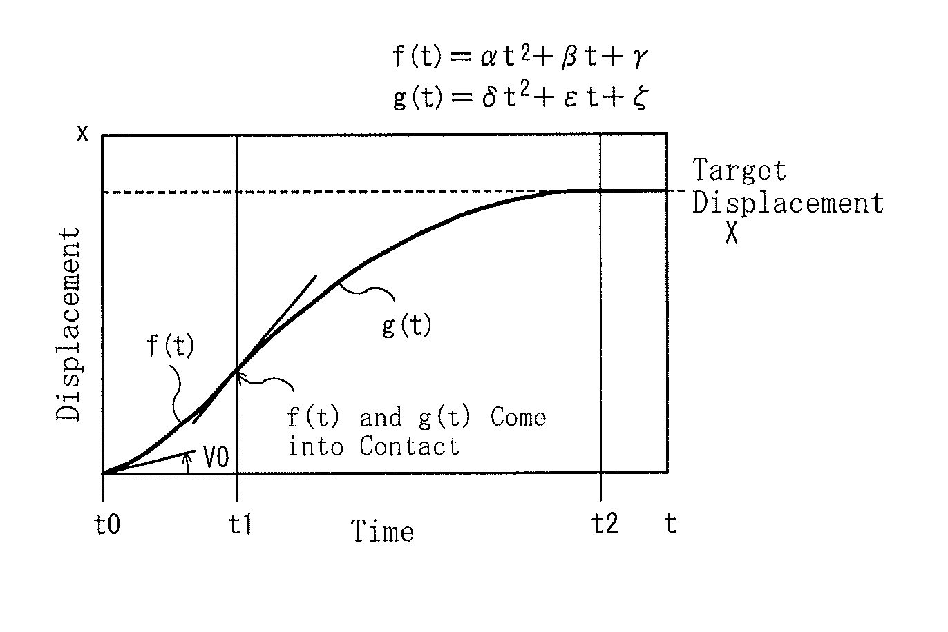
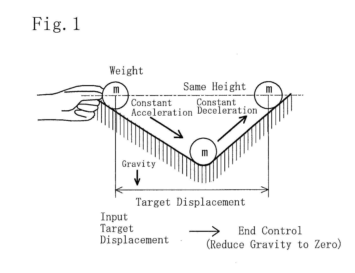
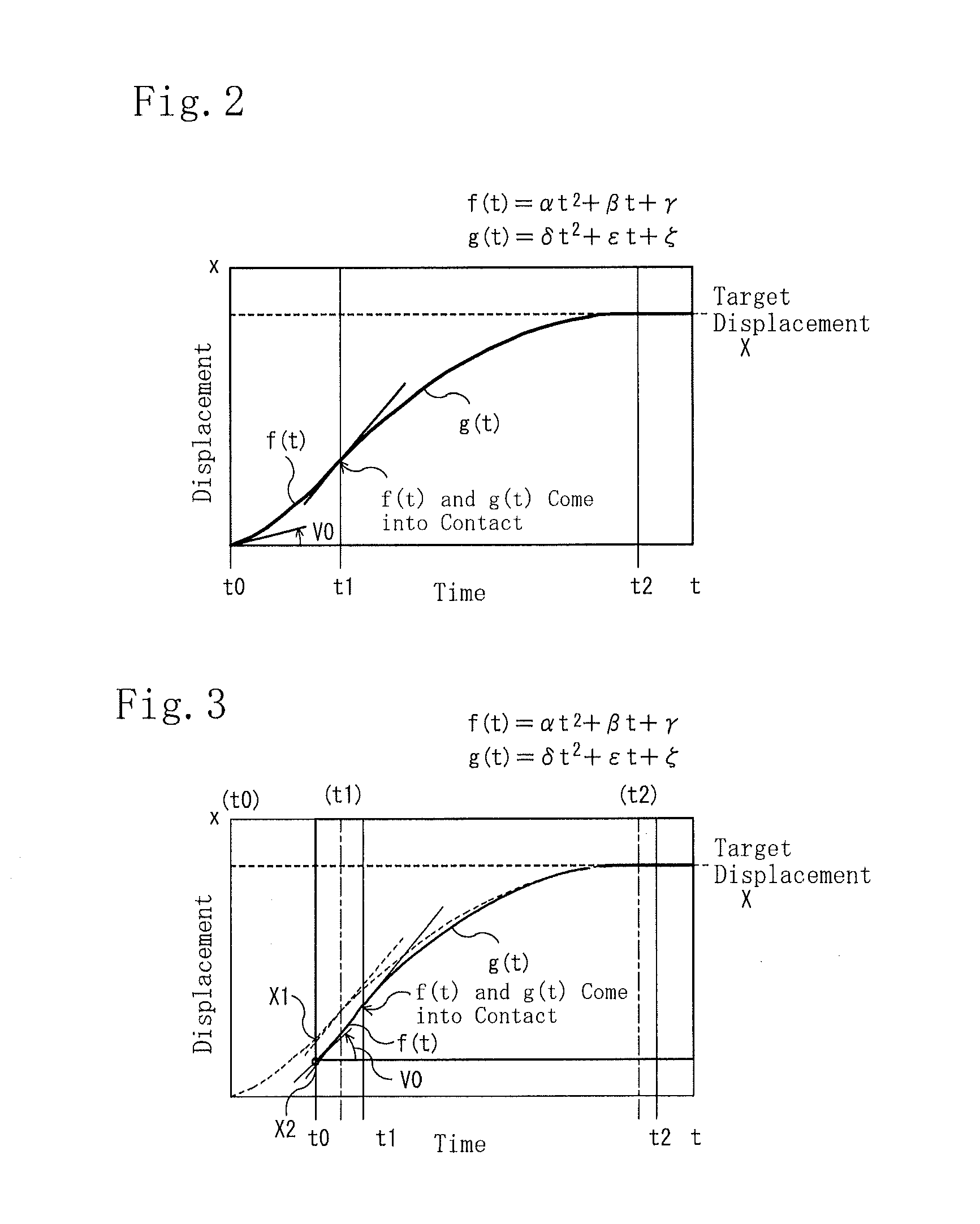
[0037]The calculation unit calculates a switching time t1 at which an acceleration output is switched to a deceleration output and an end time t2 of the deceleration output expressed by time elapsed from a calculation time t0 at which calculation for control is performed using a maximum acceleration αp and a maximum deceleration αm, which are measured in advance, at the time of a maximum output of control force of the actuator.

[0038]Moreover, the control output unit sets the control force of the ac...


PUM


Abstract

An actuator control method and an actuator control device that incorporate an element of feedback control in time optimal control, including: a calculation step of calculating a switching time at which an acceleration output is switched to a deceleration output and an end time of the deceleration output expressed by time elapsed from a calculation time at which calculation for control is performed using a maximum acceleration and a maximum deceleration, which are measured in advance, at the time of the maximum output of control force of an actuator; a control output step of setting the control force of the actuator to a maximum acceleration output from the calculation time to the switching time, setting the control force of the actuator to a maximum deceleration output from the switching time to the end time, and ending the output of the control force at the end time, and an update step of calculating and updating the switching time and the end time by repeating the calculation step at each preset time.

Description

TECHNICAL FIELD[0001]The present invention relates to an actuator control method and an actuator control device and, more particularly, to an actuator control method and an actuator control device capable of incorporating the element of feedback by using a control law that modifies an output pattern at each preset time in time optimal control.BACKGROUND ART[0002]In the conventional control, the feedback control of PID control has been generally used. In the PID control, a control output is always determined with a delay from a phenomenon, and therefore, if each control gain of PID is increased in an attempt to increase the control speed, the control no longer catches up with the phenomenon, and therefore, the control becomes unstable. In particular, if a mechanical damping force of a controlled object reduces remarkably, the control tends to become unstable and there is a case where the control diverges. As a method for determining each control gain of the PID control in order to av...

Claims


Application Information

Patent Timeline
IPC IPC(8): H01H9/00
CPCH01H9/00G05B19/416G05B2219/39357G05B2219/41086G05B2219/41087G05B2219/43041G05B2219/43045G05B2219/43099G05B2219/43112G05B2219/43114
Inventor YAMAMOTO, YASUSHI
Owner ISUZU MOTORS LTD
Why Eureka
Try Eureka