Display device including a multifunctional and communicating surface

a multi-functional, communicating surface technology, applied in the direction of instruments, optics, cathode-ray tube indicators, etc., can solve the problems of hammering the quality of the detection of contacts on the screen, the cost of transparent tco materials remains high, and the inability to guarantee their future availability at reasonable costs

Active Publication Date: 2014-09-11
GARMIN
View PDF6 Cites 31 Cited by
  • Summary
  • Abstract
  • Description
  • Claims
  • Application Information

AI Technical Summary

Benefits of technology

[0065]Alternatively, it will be possible to implement an optical function, in which the functional elements will consist of a network of optical microfibers suitable for picking up the image of the fingerprints when a finger is placed on an appliance equippe...

Problems solved by technology

This integration of the keyboard function in the screen of a cell phone or similar, raises a first series of problems when it is done according to techniques most widely used to produce touch screens.
Now, the materials of TCO type, although they are transparent and do not therefore interfere with the image displayed on the screen, are not very good conductors of electricity, which hampers the quality of the detection of the contacts on the screen.
Furthermore, the cost of the transparent TCO materials is still high and their future availability at reasonable costs does not appear guaranteed, with risks of scarcity of TCO on the market in the next few years.
However, there is then an a priori prohibitive technical problem, in that the conductive metal lines are not transparent.
Consequently, the network of lines of the touch screen would then be visible in the displayed image, which would obviously be unacceptable.
Another complementary issue arises from the relatively large size of the screens in most of the modern portable electronic devices.
This form factor is becoming increa...

Method used


Image

  • Display device including a multifunctional and communicating surface
  • Display device including a multifunctional and communicating surface
  • Display device including a multifunctional and communicating surface

Examples


Embodiment Construction

[0073]The invention is now described in more detail with the help of the description of the indexed FIGS. 1 to 6, in which:

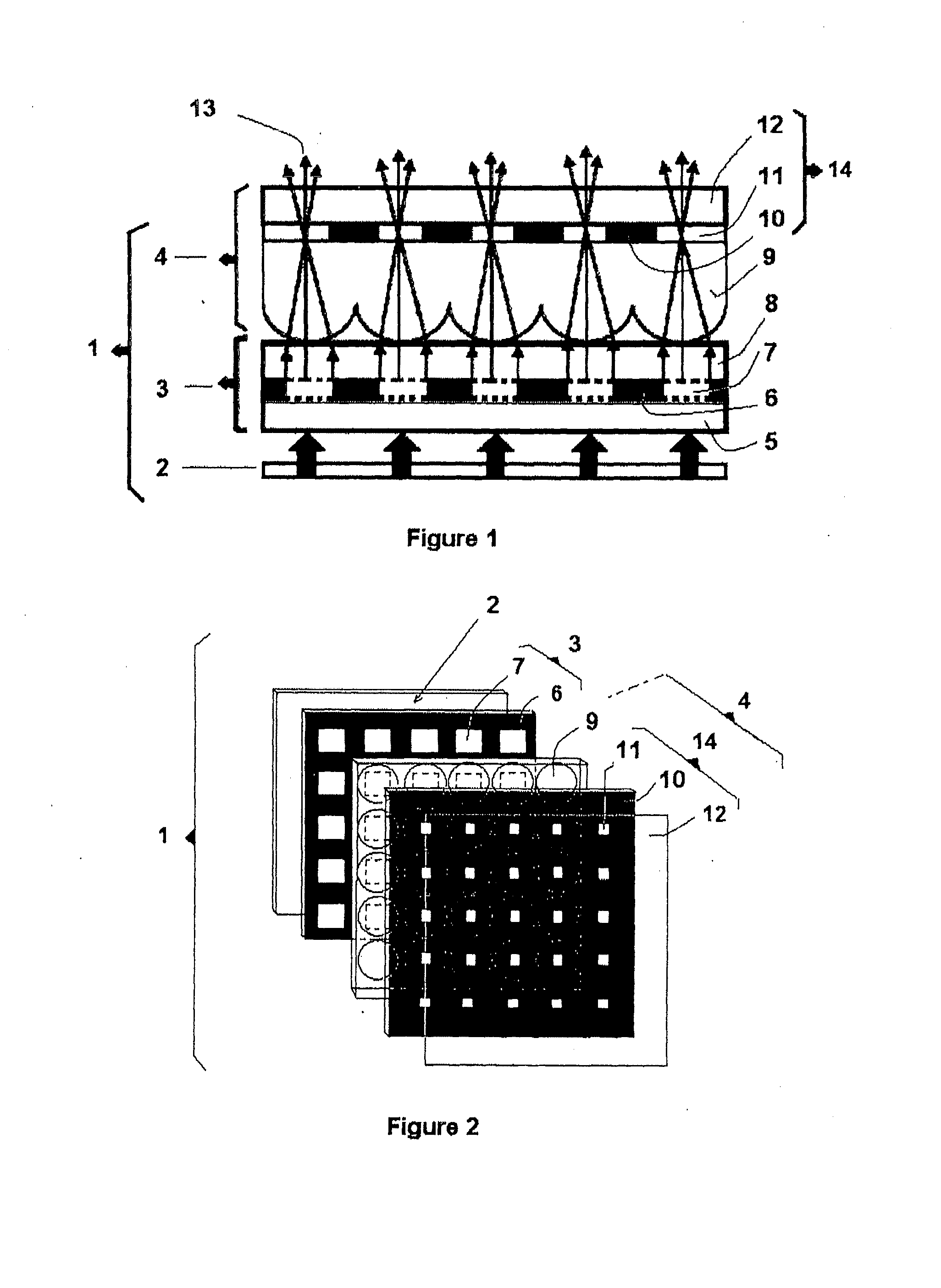
[0074]FIG. 1 is a cross-sectional diagram of a display device implementing the optical principle of the invention;

[0075]FIG. 2 is a perspective illustration of the different layers that make up the device according to the invention;

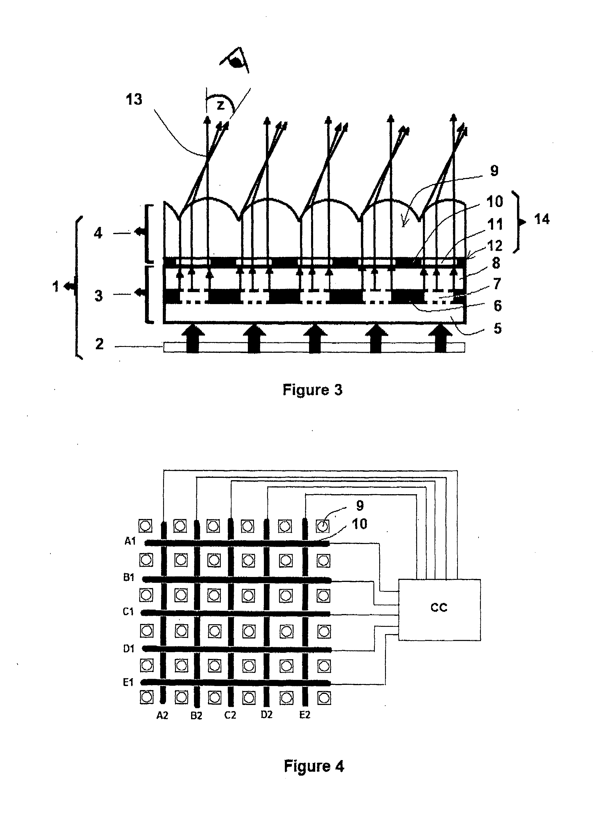
[0076]FIG. 3 is a cross-sectional diagram of an optical variant of the display device according to the invention;

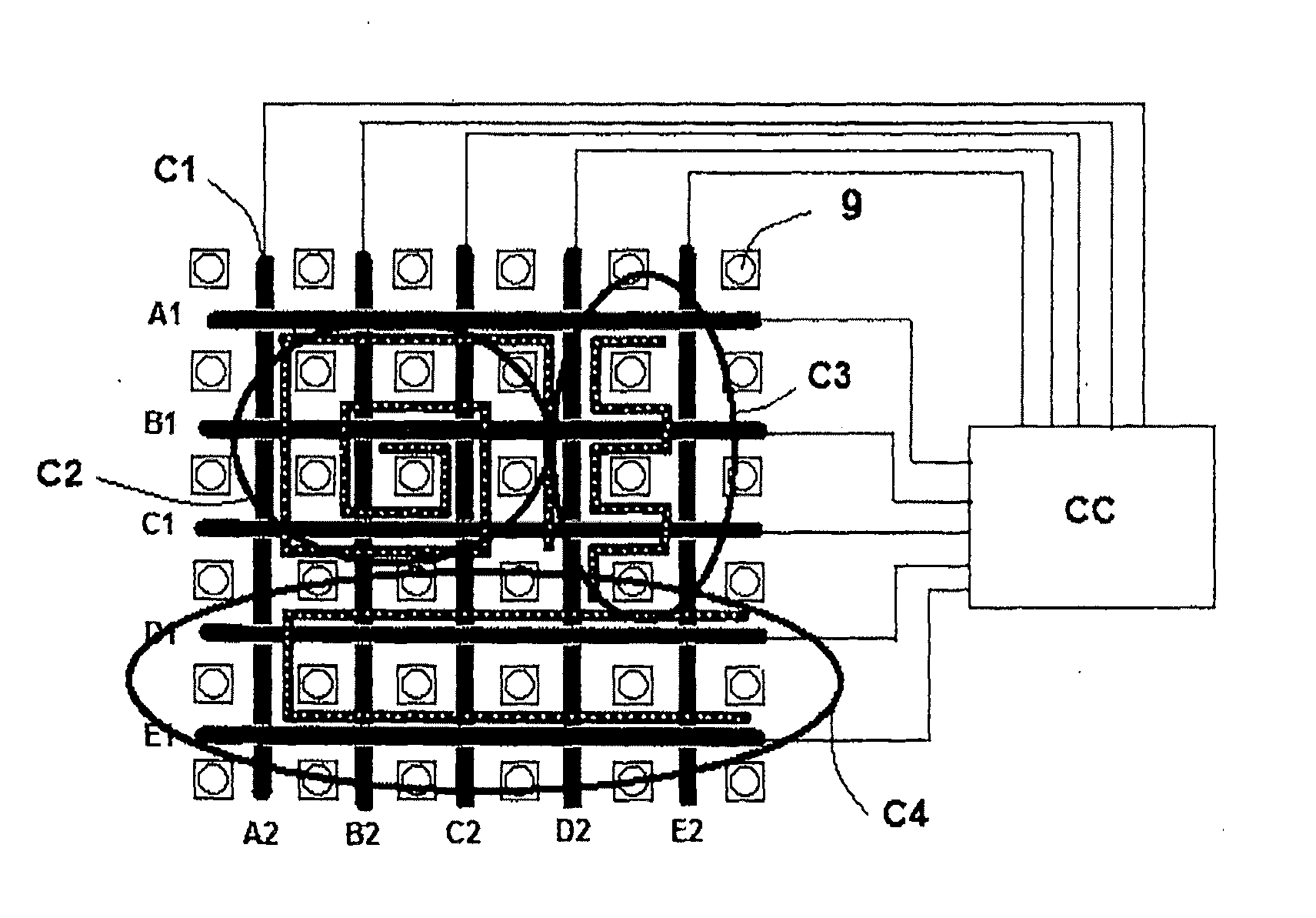
[0077]FIG. 4 illustrates a particular form of thin electronic layer with touch function;

[0078]FIG. 5 illustrates a particular form of thin electronic layer with emission / reception antenna functions;

[0079]FIG. 6 illustrates a particular form of combinations of a plurality of interweaved thin electronic and / or mechanical layers.

[0080]The display device (1) according to the invention consists on the one hand of a display screen (3) whose pixels (7) are either lit by the ambient light, or backlit by a rear lighting device (2), ...


PUM


Abstract

The invention relates to a display device including a plurality of pixels forming an image, and an optical plate arranged opposite the image and having transparency areas configured to allow the light from the pixels to at least partially pass therethrough. The optical plate further includes at least one array of functional elements corresponding to an electronic and/or mechanical function. The functional elements are inserted between the transparency areas and arranged such that the light emitted by the pixels is directed so as to pass through the transparency areas without intercepting the arrays of functional elements, so as to render the arrays of functional elements invisible or quasi-invisible to an observer of the display device. The invention can be used in any type of display device in which functions other than display itself must be integrated in a visually discreet manner.

Description

[0001]The present invention relates to display devices and, more particularly, to interactive images and to display screens such as those of cell phones, computers, GPS location devices, communication tablets, electronic newspapers, urban advertising, without this list being limiting.STATE OF THE ART[0002]The communication between, for example, a device provided with a display screen and a user can traditionally take place via an interface of the type comprising a manual keyboard, electronic mouse, joysticks, touch medium, microphone, physical or chemical sensor, including communication by radio waves or by infrared.[0003]However, more and more frequently, from the point of view of the usage made by the user, the aim is to optimize the size of the screen of a device, notably with respect to cell phones, while minimizing the size and the visual impact of the components providing functions other than the display function.[0004]This trend has been particularly notable in recent years i...

Claims


Application Information

Patent Timeline
IPC IPC(8): G09G3/34
CPCG02F1/13338G02F1/133526G09G2360/147G09G3/3406G06F3/0412
Inventor GILBERT, JOEL
Owner GARMIN
Why Eureka
Try Eureka