Porous gas permeable material for gas separation

a gas separation and permeable material technology, applied in the direction of separation process, membrane, filtration separation, etc., can solve the problems of not having attempted to create holes of a specific size, nothing in previous approaches that included steps, etc., to achieve high selectivity, high permeance, and large volume fraction porosity

Inactive Publication Date: 2005-09-22
GAS SEPARATION TECH
View PDF18 Cites 37 Cited by
  • Summary
  • Abstract
  • Description
  • Claims
  • Application Information

AI Technical Summary

Benefits of technology

[0007] It is an object of this invention to provide a process for producing gas separation membranes having high selectivity achieved by having controlled pore sizes and narrow pore size distributions, and high permeance, defined as flux / pressure drop, achieved by having a large volume fraction porosity and a very thin selective layer.

Problems solved by technology

Organic membrane materials allow the passage of only certain molecules, but this passage is typically controlled by a solution diffusion mechanism, which is too slow (partition coefficients allow flows of 2-3 l / ft2 / day which are insufficient) a process for this approach to be used in many industrial gas separation applications.
However, these methods have never attempted to create holes of a specific size, and for the specific purpose of separating two or more well-defined gases.
Furthermore, there has been nothing in previous approaches that included the steps of first, selecting the hole size desired, and second, creating a porous material containing this hole size.

Method used


Image

  • Porous gas permeable material for gas separation
  • Porous gas permeable material for gas separation
  • Porous gas permeable material for gas separation

Examples


example 1

[0119] Oxygen having a working diameter of 3.46 Å (a pore diameter of 3.55 Å is used for ease of passage) has an area of A=(12⁢D)2⁢πApore=(3.55⁢ ⁢A2)2⁢π=(1.77)2⁢π=9.84⁢ ⁢A1⁢ ⁢square⁢ ⁢meter=1010×1010⁢ ⁢Å2=1020⁢ ⁢Å25⁢%⁢ ⁢open=.05×1020⁢ ⁢Å2[0120] number of pores is .05×1020⁢A29.90⁢ ⁢A2=5.05×10¹⁷

(1.77 Å produces an Apore=9.84 Å whereas 1.78 Å produces an Apore=9.95 Å, so an average of 9.90 Å is used)

Time of passage taken as 1×10⁻⁶ sec; then 5.05×10171×10-6=5.05×10²³[0121] molecules per second [0122] 5.05×10²³ molecules of oxygen per second

One mole of oxygen is 32 grams. Avagadro's number is 6.02×10²³

Therefore: 5.05×10236.02×1023×32=0.83⁢ ⁢mole×32⁢ ⁢g⁢ / ⁢mole=26.6⁢ ⁢g⁢ / ⁢sec.

Per day: 0.83 mole / sec of oxygen gives since

24 hours is 84,600 sec

this is: [0123] 0.83 mole / sec×84,600 sec=70,218 moles [0124]×32 g / mole=(71,903,232 g / day / m2) (158,203 lbs. / day / m2) (79.1 tons / day / m2)

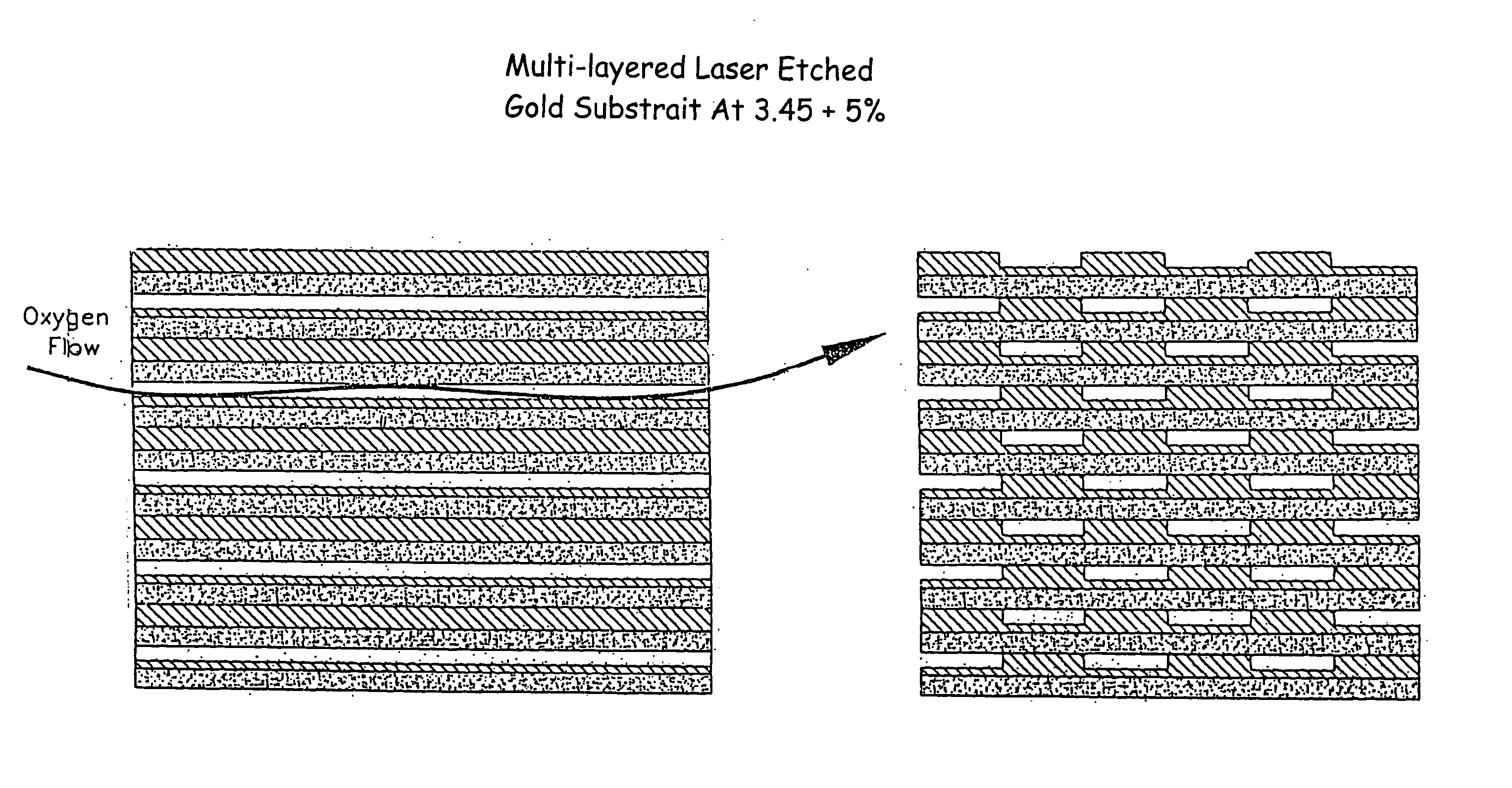
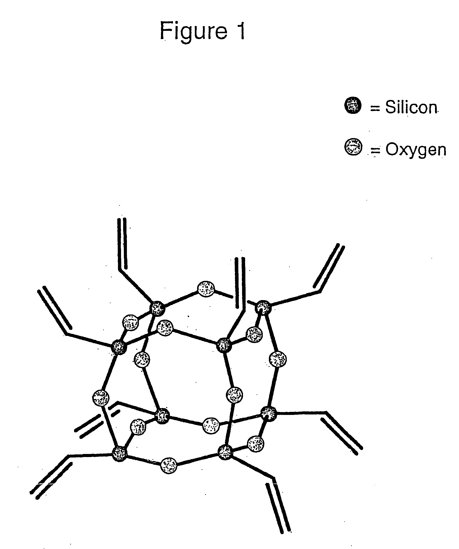
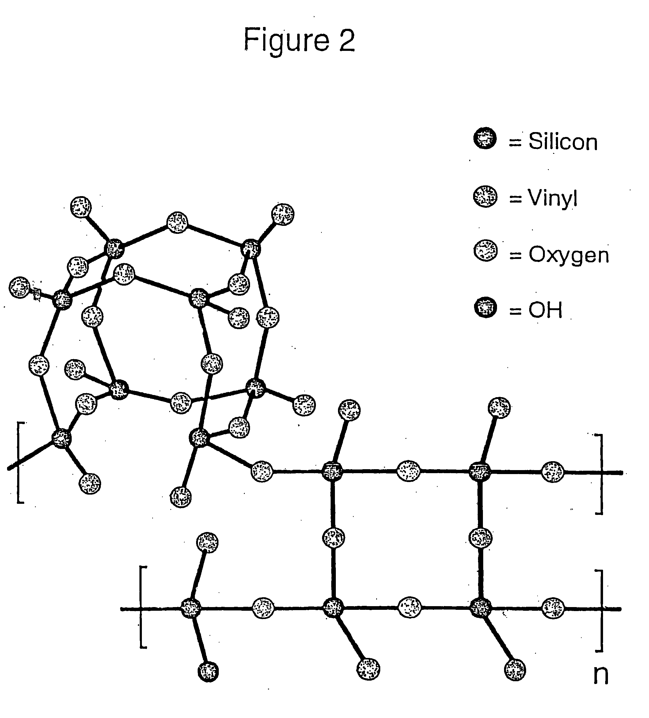
[0125] Although many methods of synthesis for the gas separator are possible, a silicon oxygen polymeri...

example 2

[0132] A porous film is prepared by mixing 30 wt % of octa vinyl POSS with 68 wt % polydimethylsiloxane (a silicone film former) and curing with 2 wt % benzoyl peroxide at 60° C. for 1 hour. The combined mixture is coated on a 0.2 mμ stainless steel filter support.

example 3

[0133] A porous film for separating carbon dioxide and methane is prepared by mixing 40 wt % gamma-cyclodextrin-hydroxypropyl derivative with 60 wt % VixTx (POSS vinyl resin). This mixture is dissolved in denatured alcohol and cast into a film on a 0.2 mμ stainless steel support. No curing agent is required.


PUM

PropertyMeasurementUnit
Timeaaaaaaaaaa
diameteraaaaaaaaaa
sizesaaaaaaaaaa

Abstract

A gas separator, a method for producing the gas separator, and a method for separating gases based on a property of inelasticity of the gases. The inventive gas separator is a permeable porous material for separating a mixture of gases by selectable pore size exclusion, comprising pores formed with at least one nanostructured compound. In other words, the inventive porous material can be used to separate a mixture of gases based upon the different working diameter of each of the gases. By selecting specific nanostructured compounds, the porous material can be tailored to contain pores of a predetermined size which allow gases having a working diameter smaller than the size of the pores to pass through the material while preventing the passage of gases having a working diameter greater than the size of the pores.

Description

BACKGROUND OF THE INVENTION [0001] 1. Field of the Invention [0002] The present invention relates to a gas separator for gas separation, a method for preparing the gas separator, and a method of performing gas separation. [0003] 2. Description of the Related Art [0004] It has been determined that there are limits to the compressibility of gas molecules, a fact which is commonly known as the law of incompressibility of matter. Based on this law, it has further been found that gas molecules behave as if they have some minimum diameter, known as their “working diameter”. [0005] If it is desired to separate one species of gas from others, for any one of many reasons (e.g., enhanced combustion, gas recovery, pollution control, etc.), it has been realized for some time that the ideal separation mechanism would pass one gaseous component in a mixture, while rejecting all others in a continuous steady-state manner. Organic membrane materials allow the passage of only certain molecules, but ...

Claims


Application Information

Patent Timeline
Patent Type & Authority Applications(United States)
IPC IPC(8): B01D53/22B01D67/00B01D69/02B01D69/14B01D71/02B01D71/70B01D71/82C01B3/50C01B13/02
CPCB01D53/228B01D2325/20B01D67/0072B01D69/02B01D69/141B01D71/022B01D71/028B01D71/70B01D71/82C01B3/503C01B13/0255C01B2210/0046C01B2210/0062Y10S977/888Y10S977/902Y10S977/926Y10S55/05B01D2323/24B01D2325/02B01D2325/08B01D67/0058
Inventor SAMMONS, JACKGODDARD, DAVID M.
Owner GAS SEPARATION TECH
Why Eureka
Try Eureka