
Methods and structures for forming and improving solder joint thickness and planarity control features for solar cells

Active Publication Date: 2014-01-28
MAXEON SOLAR PTE LTD
View PDF135 Cites 37 Cited by
  • Summary
  • Abstract
  • Description
  • Claims
  • Application Information

AI Technical Summary

Benefits of technology

The invention proposes a solution to prevent failure of thin solder layers in electronic devices. By adding a thicker layer of solder around the thin layer, cracks that might develop within the solder layer can be reduced or eliminated. This results in a stronger and more reliable connection between components in the device.

Problems solved by technology

Inspection of failed solar cell arrays has revealed that the failure of the solder layer appears to emanate from these thin areas of a wedge-shaped solder layer.

Method used


Image

  • Methods and structures for forming and improving solder joint thickness and planarity control features for solar cells
  • Methods and structures for forming and improving solder joint thickness and planarity control features for solar cells
  • Methods and structures for forming and improving solder joint thickness and planarity control features for solar cells

Examples


Embodiment Construction

[0047]The following detailed description is merely illustrative in nature and is not intended to limit the embodiments of the subject matter or the application and uses of such embodiments. As used herein, the word “exemplary” means “serving as an example, instance, or illustration.” Any implementation described herein as exemplary is not necessarily to be construed as preferred or advantageous over other implementations. Furthermore, there is no intention to be bound by any expressed or implied theory presented in the preceding technical field, background, brief summary or the following detailed description.

[0048]In addition, certain terminology can also be used in the following description for the purpose of reference only, and thus is not intended to be limiting. For example, terms such as “upper”, “middle”, and “lower” refer to directions in the drawings to which reference is made. Terms such as “front” and “back” describe the orientation and / or location of portions of the compo...


PUM

PropertyMeasurementUnit
Forceaaaaaaaaaa
Lengthaaaaaaaaaa
Heightaaaaaaaaaa

Abstract

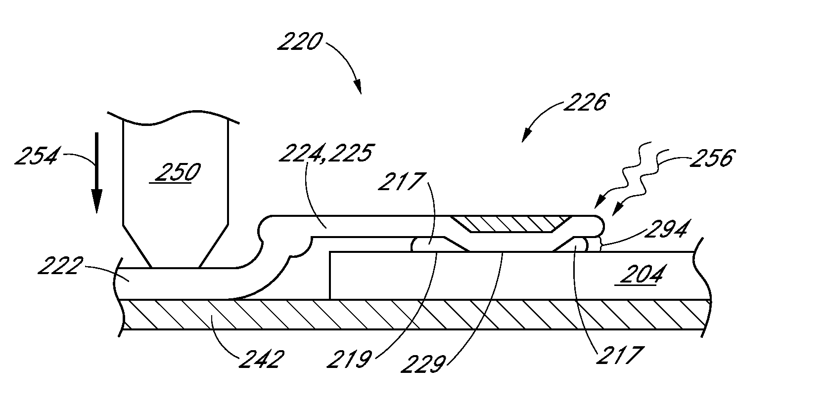
A method for connecting a plurality of solar cells and an improved interconnect is disclosed. The method includes aligning an interconnect to a plurality of solar cells having solder pads, where the interconnect has a main body and tabs extending therefrom, and where each of the tabs has a downward depression, such that the tabs are positioned above the solder pads in between solar cells and pinning the interconnect against a work surface by pressing a hold down pin against the main body of the interconnect such that a lower surface of the interconnect tabs are maintained parallel to an upper surfaces of the solder pads, and such that the depression of each of the tabs flatly contacts the solder pads. The method can also include cantilevered tabs extending downwardly from the main body providing a controlled spring force between the tab lower surface and the solder pad upper surface.

Description

CROSS-REFERENCE TO RELATED APPLICATIONS[0001]This application claims the priority of U.S. Provisional Patent Application No. 61 / 707,851, filed Sep. 28, 2012, entitled “METHODS AND STRUCTURES FOR FORMING AND IMPROVING SOLDER JOINT THICKNESS AND PLANARITY CONTROL FEATURES FOR SOLAR CELLS,” the disclosure of which is incorporated by reference herein in its entirety and for all purposes.TECHNICAL FIELD[0002]Embodiments of the subject matter described herein relate generally to photovoltaic assemblies including solar cells, photovoltaic modules and associated electronic components. More particularly, one or more embodiments of the present inventions relate to electrically connecting a plurality of solar cells in preparation for installation into photovoltaic modules.BACKGROUND[0003]Solar cells are well known devices for converting solar radiation to electrical energy. Several solar cells can be electrically connected together using one or more interconnects to form a solar cell array. Th...

Claims


Application Information

Patent Timeline
IPC IPC(8): B23K31/02
CPCB23K2203/10B23K1/0016B23K1/012H01L31/0508B23K1/002H01L24/34B23K2203/12B23K2201/38B23K31/02H01L24/36H01L24/40B23K2103/12B23K2101/38B23K2103/10H01L2224/40137H01L2224/37144H01L24/37H01L2224/37124H01L2224/37147H01L2224/37139H01L2224/3754Y02E10/50H01L24/77H01L24/84H01L2224/84801
Inventor LINDERMAN, RYANPHU, THOMAS
Owner MAXEON SOLAR PTE LTD
Learn More